
Service Manual
Page 2
... Model Number Nomenclature ...3 Symbols Used in this Manual ...4 Safety Precautions...5 Dimensions...11 Indoor Unit...11 Outdoor Unit ...12 Product Specifications ...13 Installation ...15 Installation Parts...15 Installation Tools...15 Select the best location ...16 Piping length and elevation ...17 Fixing Installation Plate(Standart Type 18 Preparing work for Installation (Artcool Type Only 19 Flaring Work and...
... Model Number Nomenclature ...3 Symbols Used in this Manual ...4 Safety Precautions...5 Dimensions...11 Indoor Unit...11 Outdoor Unit ...12 Product Specifications ...13 Installation ...15 Installation Parts...15 Installation Tools...15 Select the best location ...16 Piping length and elevation ...17 Fixing Installation Plate(Standart Type 18 Preparing work for Installation (Artcool Type Only 19 Flaring Work and...

Service Manual
Page 5
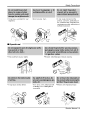
...• Do not disassemble or repair the product. Install the panel and the cover Always install a dedicated cir- cuit and breaker. Be sure to properties only. I Incorrect operation due to do. Use this manual are as shown below. Service Manual 5 er or fuse. • There is risk ...of fire or electric shock. • Improper wiring or installation may • There is risk of injury or damage to follow the...
...• Do not disassemble or repair the product. Install the panel and the cover Always install a dedicated cir- cuit and breaker. Be sure to properties only. I Incorrect operation due to do. Use this manual are as shown below. Service Manual 5 er or fuse. • There is risk ...of fire or electric shock. • Improper wiring or installation may • There is risk of injury or damage to follow the...
Service Manual
Page 9
...to lift and transport the product. Do not use the product for your health. Wax Thinner Service Manual 9 Do not use harsh detergents, solvents, etc. Use two or more people to clean. Do not install the product where it will be exposed to sea wind (salt spray) directly. • Avoid ...There is risk of fire, electric shock, or damage to your neighbors. Do not touch the metal parts of air flow. Safety Precautions Do not install the product where the noise or hot air from the outdoor unit could damage the neighborhoods. • It may cause a problem for special purposes,...
...to lift and transport the product. Do not use the product for your health. Wax Thinner Service Manual 9 Do not use harsh detergents, solvents, etc. Use two or more people to clean. Do not install the product where it will be exposed to sea wind (salt spray) directly. • Avoid ...There is risk of fire, electric shock, or damage to your neighbors. Do not touch the metal parts of air flow. Safety Precautions Do not install the product where the noise or hot air from the outdoor unit could damage the neighborhoods. • It may cause a problem for special purposes,...
Service Manual
Page 11
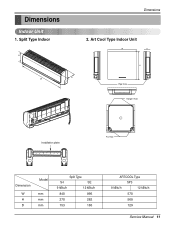
Art Cool Type Indoor Unit W D H Pipe Hole Hanger Hole Installation plate Fix Hole Dimension W H D Model mm mm mm Split Type S4 SE 9 kBtu/h 12 kBtu/h 840 895 270 282 153 165 ARTCOOL Type SP3 9 kBtu/h 12 kBtu/h 570 568 129 Service Manual 11 Split Type Indoor H D W Dimensions 2. Dimensions Indoor Unit 1.
Art Cool Type Indoor Unit W D H Pipe Hole Hanger Hole Installation plate Fix Hole Dimension W H D Model mm mm mm Split Type S4 SE 9 kBtu/h 12 kBtu/h 840 895 270 282 153 165 ARTCOOL Type SP3 9 kBtu/h 12 kBtu/h 570 568 129 Service Manual 11 Split Type Indoor H D W Dimensions 2. Dimensions Indoor Unit 1.
Service Manual
Page 15
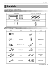
Installation Read carefully, and then follow step by step. Installation Parts Installation plate Type "B" screw Installation Type "A" screw and plastic anchor Remote Control Holder Installation Tools Figure Name Screw driver Electric Drill Measuring Tape, Knife Hole Core Drill Spanner Torque wrench Figure Name Ohmmeter Hexagonal wrench Ammeter Gas Leak Detector Thermometer, Level Flaring Tool Set Service Manual 15
Installation Read carefully, and then follow step by step. Installation Parts Installation plate Type "B" screw Installation Type "A" screw and plastic anchor Remote Control Holder Installation Tools Figure Name Screw driver Electric Drill Measuring Tape, Knife Hole Core Drill Spanner Torque wrench Figure Name Ohmmeter Hexagonal wrench Ammeter Gas Leak Detector Thermometer, Level Flaring Tool Set Service Manual 15
Service Manual
Page 17
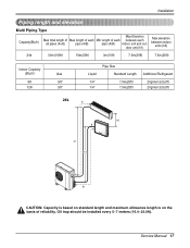
Oil trap should be installed every 5~7 meters (16.4~23.0ft). Service Manual 17 door unit (h1) Max elevation between each between indoor units (h2) 24k 30m(100ft) 15m(50ft) 3m(10ft) 7.5m(25ft) 7.5m(25ft) Indoor Capacity (.../ft) 20g/m(0.32oz/ft) 24k A h2 B h1 h1 B CAUTION: Capacity is based on standard length and maximum allowance length is on the basis of reliability. Installation Piping length and elevation Multi Piping Type Capacity(Btu/h) Max Elevation Max total length of Max length of each Min length of each all pipes...
Oil trap should be installed every 5~7 meters (16.4~23.0ft). Service Manual 17 door unit (h1) Max elevation between each between indoor units (h2) 24k 30m(100ft) 15m(50ft) 3m(10ft) 7.5m(25ft) 7.5m(25ft) Indoor Capacity (.../ft) 20g/m(0.32oz/ft) 24k A h2 B h1 h1 B CAUTION: Capacity is based on standard length and maximum allowance length is on the basis of reliability. Installation Piping length and elevation Multi Piping Type Capacity(Btu/h) Max Elevation Max total length of Max length of each Min length of each all pipes...
Service Manual
Page 19
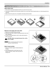
... the cover side of cover side. Remove two screws(for safety. Pipe hole Adhesive Only one desiring direction Connecting part Drain hose rubber cap Service Manual 19 Remove the rubber stopple of desired direction of drain pan, and join drain hose and connecting hose. NOTICE When connecting pipe path through the...
... the cover side of cover side. Remove two screws(for safety. Pipe hole Adhesive Only one desiring direction Connecting part Drain hose rubber cap Service Manual 19 Remove the rubber stopple of desired direction of drain pan, and join drain hose and connecting hose. NOTICE When connecting pipe path through the...
Service Manual
Page 20
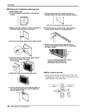
... connect the pipe and the wire. (Installation manual reference) I Sticking the installation guide map and fixing Indoor unit 1. Installation I Drill a hole in the wall • Drill the piping hole with a ø50mm hole core drill. Put an Installation Guide Map on the horizontal setting line,...screws. (In this page when making a hole in the wall. 8. Drive the fore plastic anchors into drilled points. Horizontality INSTALLATION GUIDE MAP Indoor WALL Outdoor 5-7mm (0.2~0.3") 20 Multi type Air Conditioner INSTAIIATION GUIDE MAP 3. Look at suited horizon by horizontal meter...
... connect the pipe and the wire. (Installation manual reference) I Sticking the installation guide map and fixing Indoor unit 1. Installation I Drill a hole in the wall • Drill the piping hole with a ø50mm hole core drill. Put an Installation Guide Map on the horizontal setting line,...screws. (In this page when making a hole in the wall. 8. Drive the fore plastic anchors into drilled points. Horizontality INSTALLATION GUIDE MAP Indoor WALL Outdoor 5-7mm (0.2~0.3") 20 Multi type Air Conditioner INSTAIIATION GUIDE MAP 3. Look at suited horizon by horizontal meter...
Service Manual
Page 23
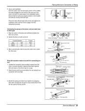
... 3/8 Torque kg.m 1.8 4.2 3. Press the lower left and right. Tighten the flare nut with vinyl tape Drain hose Vinyl tape(wide) Service Manual 23 Flaring Work and Connection of the indoor unit with vinyl tape for enough to drain pipe. 1. Align the center of the pipes and sufficiently...section. 4. Wrap the area which accommodates the rear piping housing section with vinyl tape so that the hooks are properly seated on the installation plate by hand. 2. Bundle the piping and drain hose together by wrapping them together with vinyl tape. 3. Wrap the insulation material ...
... 3/8 Torque kg.m 1.8 4.2 3. Press the lower left and right. Tighten the flare nut with vinyl tape Drain hose Vinyl tape(wide) Service Manual 23 Flaring Work and Connection of the indoor unit with vinyl tape for enough to drain pipe. 1. Align the center of the pipes and sufficiently...section. 4. Wrap the area which accommodates the rear piping housing section with vinyl tape so that the hooks are properly seated on the installation plate by hand. 2. Bundle the piping and drain hose together by wrapping them together with vinyl tape. 3. Wrap the insulation material ...
Service Manual
Page 25
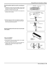
... until the hooks engage into the rear piping housing section. Piping for passage through piping hole Connecting cable Drain hose Service Manual 25 Remove the spacer. 2. Press the lower left and right. 3. Reroute the pipings and the drain hose across the back of ...cloth tape over the range within which accommodates the rear piping housing section with vinyl tape so that the hooks are properly seated on the installation plate by wrapping them together with vinyl tape. 3. Flaring Work and Connection of the chassis. Wrap the insulation material around the connecting portion....
... until the hooks engage into the rear piping housing section. Piping for passage through piping hole Connecting cable Drain hose Service Manual 25 Remove the spacer. 2. Press the lower left and right. 3. Reroute the pipings and the drain hose across the back of ...cloth tape over the range within which accommodates the rear piping housing section with vinyl tape so that the hooks are properly seated on the installation plate by wrapping them together with vinyl tape. 3. Flaring Work and Connection of the chassis. Wrap the insulation material around the connecting portion....
Service Manual
Page 27
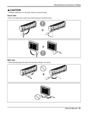
Follow the instruction below. Bad case • Following bending type from right to left piping. Good case • Press on the upper side of Piping Installation Information. Flaring Work and Connection of clamp and unfold the tubing to the tubing. For left may cause damage to downward slowly. Service Manual 27
Follow the instruction below. Bad case • Following bending type from right to left piping. Good case • Press on the upper side of Piping Installation Information. Flaring Work and Connection of clamp and unfold the tubing to the tubing. For left may cause damage to downward slowly. Service Manual 27
Service Manual
Page 35
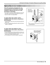
... the piping by saddle or equivalent. Trap Trap Service Manual 35 In cases where the outdoor unit is required to up . 2. Taping Drain hose Plastic band Pipings Connecting cable Power supply cord • Trap is installed below the indoor unit perform the following . 1. In... cases where the Outdoor unit is installed above the ground. Seal a small opening around the pipings with gum type sealer. Secure ...
... the piping by saddle or equivalent. Trap Trap Service Manual 35 In cases where the outdoor unit is required to up . 2. Taping Drain hose Plastic band Pipings Connecting cable Power supply cord • Trap is installed below the indoor unit perform the following . 1. In... cases where the Outdoor unit is installed above the ground. Seal a small opening around the pipings with gum type sealer. Secure ...
Service Manual
Page 39
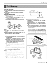
...is more than 5 minutes without fail. (Test run will be operated. Check that the gas and liquid side service valves are installed correctly. Insert new batteries making sure that all tubing and wiring have been properly connected. 2. Bolt Tubing connection 4) Evaluation of... TEMP. Measure the pressure of air. 3. I .G.) Intake temperature Discharge air Discharge air Discharge temperature Intake temperature Discharge temperature Service Manual 39 Test Running Test Running Split, Art Cool Type 1. Do not use rechargeable batteries. • Remove the batteries from the remote...
...is more than 5 minutes without fail. (Test run will be operated. Check that the gas and liquid side service valves are installed correctly. Insert new batteries making sure that all tubing and wiring have been properly connected. 2. Bolt Tubing connection 4) Evaluation of... TEMP. Measure the pressure of air. 3. I .G.) Intake temperature Discharge air Discharge air Discharge temperature Intake temperature Discharge temperature Service Manual 39 Test Running Test Running Split, Art Cool Type 1. Do not use rechargeable batteries. • Remove the batteries from the remote...
Service Manual
Page 81
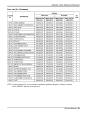
...,TUBING 5211A21363E 5211A21363E 5211A15008A 5211A15008A R 352150 HOSE ASSEMBLY,DRAIN 5251A20011B 5251A20011B 5251A20011G 5251A20011G R 359011 FAN ASSEMBLY,CROSS FLOW 5901A20017F 5901A20017F 5901A20017H 5901A20017H R 733010 PLATE ASSEMBLY,INSTALLATION 3301A20020C 3301A20020C 3301A20020A 3301A20020A R 135500 COVER 3550A30262A 3550A30262A 3550A30315A 3550A30315A R NOTE) *Please ensure GCSC since these parts may be changed depending upon the buyer's request...
...,TUBING 5211A21363E 5211A21363E 5211A15008A 5211A15008A R 352150 HOSE ASSEMBLY,DRAIN 5251A20011B 5251A20011B 5251A20011G 5251A20011G R 359011 FAN ASSEMBLY,CROSS FLOW 5901A20017F 5901A20017F 5901A20017H 5901A20017H R 733010 PLATE ASSEMBLY,INSTALLATION 3301A20020C 3301A20020C 3301A20020A 3301A20020A R 135500 COVER 3550A30262A 3550A30262A 3550A30315A 3550A30315A R NOTE) *Please ensure GCSC since these parts may be changed depending upon the buyer's request...


