
Service Manual
Page 1
website http://www.lgservice.com LG Multi Type Air Conditioner SERVICE MANUAL MODEL • Indoor Unit: Room Type AMNH093D4A0(LMN090HE) AMNC093D4A0(LMN090CE) AMNH123DEA0(LMN120HE) AMNC123DEA0(LMN120CE) Art Cool Type AMNH093APM0(LMAN090HNS) AMNC093APM0(LMAN090CNS) AMNH123APM0(LMAN120HNS) AMNC123APM0(LMAN120CNS) • Outdoor Unit: A3UH363FA0(LMU360HE) A3UC363FA0(LMU360CE) LG CAUTION • BEFORE SERVICING THE UNIT, READ THE SAFETY PRECAUTIONS IN THIS MANUAL. • ONLY FOR AUTHORIZED SERVICE PERSONNEL.
website http://www.lgservice.com LG Multi Type Air Conditioner SERVICE MANUAL MODEL • Indoor Unit: Room Type AMNH093D4A0(LMN090HE) AMNC093D4A0(LMN090CE) AMNH123DEA0(LMN120HE) AMNC123DEA0(LMN120CE) Art Cool Type AMNH093APM0(LMAN090HNS) AMNC093APM0(LMAN090CNS) AMNH123APM0(LMAN120HNS) AMNC123APM0(LMAN120CNS) • Outdoor Unit: A3UH363FA0(LMU360HE) A3UC363FA0(LMU360CE) LG CAUTION • BEFORE SERVICING THE UNIT, READ THE SAFETY PRECAUTIONS IN THIS MANUAL. • ONLY FOR AUTHORIZED SERVICE PERSONNEL.

Service Manual
Page 2
Multi type Air Conditioner Service Manual TABLE OF CONTENTS Model Number Nomenclature ...3 Symbols Used in this Manual ...4 Safety Precautions...5 Dimensions...11 Indoor Unit...11 Outdoor Unit ...12 Product Specifications ...13 Installation ...15 Installation Parts...15 Installation Tools...15 Select the best location ......
Multi type Air Conditioner Service Manual TABLE OF CONTENTS Model Number Nomenclature ...3 Symbols Used in this Manual ...4 Safety Precautions...5 Dimensions...11 Indoor Unit...11 Outdoor Unit ...12 Product Specifications ...13 Installation ...15 Installation Parts...15 Installation Tools...15 Select the best location ......
Service Manual
Page 3
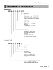
...' Model Type H: Heat Pump C: Cooling Only R-410A MPS Variable Multi System Outdoor Unit And No. of Connectable Indoor Units Ex) A3U : Connectable max. 2 Indoor Units Service Manual 3 look type N : N- look type G : G- look type L : L- Model Number Nomenclature Model Number Nomenclature Indoor Unit AMN H 09 3 D 4 A 0 Serial Number Function A : Basic, L : Nano Plasma + Auto Clean(Wall...
...' Model Type H: Heat Pump C: Cooling Only R-410A MPS Variable Multi System Outdoor Unit And No. of Connectable Indoor Units Ex) A3U : Connectable max. 2 Indoor Units Service Manual 3 look type N : N- look type G : G- look type L : L- Model Number Nomenclature Model Number Nomenclature Indoor Unit AMN H 09 3 D 4 A 0 Serial Number Function A : Basic, L : Nano Plasma + Auto Clean(Wall...
Service Manual
Page 5
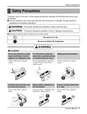
...is classified by the following instructions must be followed. Install the panel and the cover Always install a dedicated cir- cuit and breaker. or an Authorized Service Center. • There is risk of death or serious injury. of fire or electric shock. • Do not disassemble or repair the product. .... s Meanings of symbols used in this dealer, seller, a qualified electrician, appliance on a dedicated circuit. For electrical work, contact the Always ground the product. Service Manual 5 Use the correctly rated break- rated circuit breaker. Use this...
...is classified by the following instructions must be followed. Install the panel and the cover Always install a dedicated cir- cuit and breaker. or an Authorized Service Center. • There is risk of death or serious injury. of fire or electric shock. • Do not disassemble or repair the product. .... s Meanings of symbols used in this dealer, seller, a qualified electrician, appliance on a dedicated circuit. For electrical work, contact the Always ground the product. Service Manual 5 Use the correctly rated break- rated circuit breaker. Use this...
Service Manual
Page 7
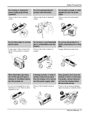
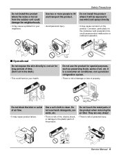
... or hurricane. Stop operation and close the window in a gas or combustibles near the power cable. • There is risk of fire or electrical shock. Service Manual 7 Safety Precautions Do not place a heater or other appliances near the tightly closed space for ventilation before the hurricane arrives. • There is risk of...
... or hurricane. Stop operation and close the window in a gas or combustibles near the power cable. • There is risk of fire or electrical shock. Service Manual 7 Safety Precautions Do not place a heater or other appliances near the tightly closed space for ventilation before the hurricane arrives. • There is risk of...
Service Manual
Page 9
... refrigeration system. • There is risk of time. (Don't sit in the draft.) • This could harm to lift and transport the product. Wax Thinner Service Manual 9 Use two or more people to your neighbors.
... refrigeration system. • There is risk of time. (Don't sit in the draft.) • This could harm to lift and transport the product. Wax Thinner Service Manual 9 Use two or more people to your neighbors.

Service Manual
Page 11
Art Cool Type Indoor Unit W D H Pipe Hole Hanger Hole Installation plate Fix Hole Dimension W H D Model mm mm mm Split Type S4 SE 9 kBtu/h 12 kBtu/h 840 895 270 282 153 165 ARTCOOL Type SP3 9 kBtu/h 12 kBtu/h 570 568 129 Service Manual 11 Dimensions Indoor Unit 1. Split Type Indoor H D W Dimensions 2.
Art Cool Type Indoor Unit W D H Pipe Hole Hanger Hole Installation plate Fix Hole Dimension W H D Model mm mm mm Split Type S4 SE 9 kBtu/h 12 kBtu/h 840 895 270 282 153 165 ARTCOOL Type SP3 9 kBtu/h 12 kBtu/h 570 568 129 Service Manual 11 Dimensions Indoor Unit 1. Split Type Indoor H D W Dimensions 2.
Service Manual
Page 13
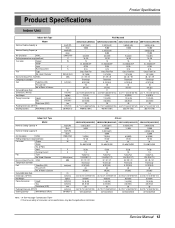
....2*25.7*9.1(665*653*231) 237/534(239/539) Note : 1.5 See the page "Combination Table" 2. of Poles Input Running Current Fan Type No. Service Manual 13 Used / Diameter Noise Level (Sound Press,1m) H/M/L Temperature controller Coil Tube Size (OD) Fins per inch No. Due to our policy of Rows...EA/inch(mm) dBA inch(mm) l/h inch(mm) kg(lbs) inch(mm) inch(mm) mm inch(mm) 20/40ft(hi-c) Wall Mounted AMNC093D4A0(LMN090CE) AMNH093D4A0(LMN090HE) AMNC123DEA0(LMN120CE) AMNH123DEA0(LMN120HE) 2,267(2,637) 9,000 - 8.2(289) 18~30 15 DL-88430LGIF DC36 0.15 Cross Flow Fan 1/3.74(95) 31 / 29 /...
....2*25.7*9.1(665*653*231) 237/534(239/539) Note : 1.5 See the page "Combination Table" 2. of Poles Input Running Current Fan Type No. Service Manual 13 Used / Diameter Noise Level (Sound Press,1m) H/M/L Temperature controller Coil Tube Size (OD) Fins per inch No. Due to our policy of Rows...EA/inch(mm) dBA inch(mm) l/h inch(mm) kg(lbs) inch(mm) inch(mm) mm inch(mm) 20/40ft(hi-c) Wall Mounted AMNC093D4A0(LMN090CE) AMNH093D4A0(LMN090HE) AMNC123DEA0(LMN120CE) AMNH123DEA0(LMN120HE) 2,267(2,637) 9,000 - 8.2(289) 18~30 15 DL-88430LGIF DC36 0.15 Cross Flow Fan 1/3.74(95) 31 / 29 /...
Service Manual
Page 15
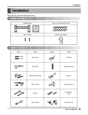
Installation Read carefully, and then follow step by step. Installation Parts Installation plate Type "B" screw Installation Type "A" screw and plastic anchor Remote Control Holder Installation Tools Figure Name Screw driver Electric Drill Measuring Tape, Knife Hole Core Drill Spanner Torque wrench Figure Name Ohmmeter Hexagonal wrench Ammeter Gas Leak Detector Thermometer, Level Flaring Tool Set Service Manual 15
Installation Read carefully, and then follow step by step. Installation Parts Installation plate Type "B" screw Installation Type "A" screw and plastic anchor Remote Control Holder Installation Tools Figure Name Screw driver Electric Drill Measuring Tape, Knife Hole Core Drill Spanner Torque wrench Figure Name Ohmmeter Hexagonal wrench Ammeter Gas Leak Detector Thermometer, Level Flaring Tool Set Service Manual 15
Service Manual
Page 17
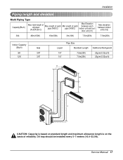
...) 20g/m(0.32oz/ft) A h2 B h2 h1 C h1 h1 CAUTION: Capacity is based on standard length and maximum allowance length is on the basis of reliability. Service Manual 17 Oil trap should be installed every 5~7 meters (16.4~23.0ft).
...) 20g/m(0.32oz/ft) A h2 B h2 h1 C h1 h1 CAUTION: Capacity is based on standard length and maximum allowance length is on the basis of reliability. Service Manual 17 Oil trap should be installed every 5~7 meters (16.4~23.0ft).
Service Manual
Page 19
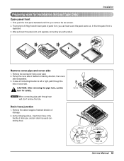
... screws(for Installation (Artcool Type Only) Open panel front 1. Drain hose junction 1. Pipe hole Adhesive Only one desiring direction Connecting part Drain hose rubber cap Service Manual 19 First, push the front panel backward and lift it up the cover side of desired connecting direction, then cover side is left or right...
... screws(for Installation (Artcool Type Only) Open panel front 1. Drain hose junction 1. Pipe hole Adhesive Only one desiring direction Connecting part Drain hose rubber cap Service Manual 19 First, push the front panel backward and lift it up the cover side of desired connecting direction, then cover side is left or right...
Service Manual
Page 21
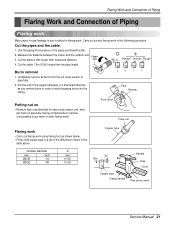
... Uneven Rough 4. Outside diameter mm inch Ø6.35 1/4 Ø9.52 3/8 A mm 0~0.5 0~0.5 Copper tube Handle "A" Bar Bar Yoke Cone Copper pipe Clamp handle Red arrow mark Service Manual 21
... Uneven Rough 4. Outside diameter mm inch Ø6.35 1/4 Ø9.52 3/8 A mm 0~0.5 0~0.5 Copper tube Handle "A" Bar Bar Yoke Cone Copper pipe Clamp handle Red arrow mark Service Manual 21

Service Manual
Page 23
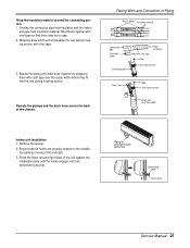
Align the center of the indoor unit with vinyl tape Drain hose Vinyl tape(wide) Service Manual 23 Bundle the piping and drain hose together by wrapping them together with vinyl tape for enough to drain pipe. 1. Wrap the insulation material around ...
Align the center of the indoor unit with vinyl tape Drain hose Vinyl tape(wide) Service Manual 23 Bundle the piping and drain hose together by wrapping them together with vinyl tape for enough to drain pipe. 1. Wrap the insulation material around ...
Service Manual
Page 25
... hooks are properly seated on the installation plate by wrapping them together with vinyl tape. 3. Piping for passage through piping hole Connecting cable Drain hose Service Manual 25 Bundle the piping and drain hose together by moving it left and right sides of the unit against the installation plate until the hooks...
... hooks are properly seated on the installation plate by wrapping them together with vinyl tape. 3. Piping for passage through piping hole Connecting cable Drain hose Service Manual 25 Bundle the piping and drain hose together by moving it left and right sides of the unit against the installation plate until the hooks...
Service Manual
Page 27
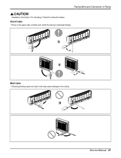
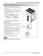
Good case • Press on the upper side of Piping Installation Information. Service Manual 27 For left may cause damage to the tubing. Flaring Work and Connection of clamp and unfold the tubing to left piping. Bad case • Following bending type from right to downward slowly. Follow the instruction below.
Good case • Press on the upper side of Piping Installation Information. Service Manual 27 For left may cause damage to the tubing. Flaring Work and Connection of clamp and unfold the tubing to left piping. Bad case • Following bending type from right to downward slowly. Follow the instruction below.
Service Manual
Page 29
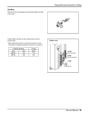
Outdoor Align the center of Piping Finally, tighten the flare nut with torque wrench until the wrench clicks. • When tightening the flare nut with torque wrench, ensure the direction for tightening follows the arrow on the wrench. Outside diameter mm inch Ø6.35 1/4 Ø9.52 3/8 Torque kg.m 1.8 4.2 Outdoor unit A-UNIT Gas side piping B-UNIT Liquid side piping C-UNIT Torque wrench Service Manual 29 Flaring Work and Connection of the pipings and sufficiently tighten the flare nut by hand.
Outdoor Align the center of Piping Finally, tighten the flare nut with torque wrench until the wrench clicks. • When tightening the flare nut with torque wrench, ensure the direction for tightening follows the arrow on the wrench. Outside diameter mm inch Ø6.35 1/4 Ø9.52 3/8 Torque kg.m 1.8 4.2 Outdoor unit A-UNIT Gas side piping B-UNIT Liquid side piping C-UNIT Torque wrench Service Manual 29 Flaring Work and Connection of the pipings and sufficiently tighten the flare nut by hand.
Service Manual
Page 31
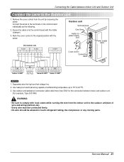
... sure to comply with local codes while running the wire from the unit by loosening the screw. Separately wire the high and low voltage line. 2. Service Manual 31 Secure the cable onto the control board with the holder (clamper). 3. Use outdoor and waterproof connection cable rated more than 300V for power supply...
... sure to comply with local codes while running the wire from the unit by loosening the screw. Separately wire the high and low voltage line. 2. Service Manual 31 Secure the cable onto the control board with the holder (clamper). 3. Use outdoor and waterproof connection cable rated more than 300V for power supply...
Service Manual
Page 33
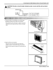
... the control board individually according to the indoor unit 1. Main power source Air Conditioner Circuit Breaker Use a circuit breaker or time delay fuse. Connecting cable 2. Service Manual 33 are the same as shown below. Connecting the Cable between Indoor Unit and Outdoor Unit CAUTION: Provide a circuit breaker between power source and the...
... the control board individually according to the indoor unit 1. Main power source Air Conditioner Circuit Breaker Use a circuit breaker or time delay fuse. Connecting cable 2. Service Manual 33 are the same as shown below. Connecting the Cable between Indoor Unit and Outdoor Unit CAUTION: Provide a circuit breaker between power source and the...
Service Manual
Page 35
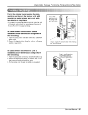
Tape the piping and connecting cable from down to up . 2. Trap Trap Service Manual 35 Taping Drain hose Plastic band Pipings Connecting cable Power supply cord • Trap is installed below the indoor unit perform the following . 1. Secure the ...
Tape the piping and connecting cable from down to up . 2. Trap Trap Service Manual 35 Taping Drain hose Plastic band Pipings Connecting cable Power supply cord • Trap is installed below the indoor unit perform the following . 1. Secure the ...
Service Manual
Page 37
...unit 2. Confirm the "Lo" knob of the pump. Then, run the vacuum pump. Loosen the charge hose connected to the gas side service port slightly to evacuate the tubing and indoor unit. This process is now ready for evacuation when 30 gal/h vacuum pump is used If tubing...a service valve wrench, turn the valve stem of the manifold valve and stop the vacuum pump. Replace the valve caps at both gas and liquid side service valves and fasten them tight. This completes air purging with a vacuum pump. Manifold valve Pressure gauge Lo Hi Open Close Vacuum pump Service Manual 37
...unit 2. Confirm the "Lo" knob of the pump. Then, run the vacuum pump. Loosen the charge hose connected to the gas side service port slightly to evacuate the tubing and indoor unit. This process is now ready for evacuation when 30 gal/h vacuum pump is used If tubing...a service valve wrench, turn the valve stem of the manifold valve and stop the vacuum pump. Replace the valve caps at both gas and liquid side service valves and fasten them tight. This completes air purging with a vacuum pump. Manifold valve Pressure gauge Lo Hi Open Close Vacuum pump Service Manual 37


