
Service Manual
Page 1
website http://www.lgservice.com LG Multi Type Air Conditioner SERVICE MANUAL MODEL • Indoor Unit: Room Type AMNH093D4A0(LMN090HE) AMNC093D4A0(LMN090CE) AMNH123DEA0(LMN120HE) AMNC123DEA0(LMN120CE) Art Cool Type AMNH093APM0(LMAN090HNS) AMNC093APM0(LMAN090CNS) AMNH123APM0(LMAN120HNS) AMNC123APM0(LMAN120CNS) • Outdoor Unit: A3UH363FA0(LMU360HE) A3UC363FA0(LMU360CE) LG CAUTION • BEFORE SERVICING THE UNIT, READ THE SAFETY PRECAUTIONS IN THIS MANUAL. • ONLY FOR AUTHORIZED SERVICE PERSONNEL.
website http://www.lgservice.com LG Multi Type Air Conditioner SERVICE MANUAL MODEL • Indoor Unit: Room Type AMNH093D4A0(LMN090HE) AMNC093D4A0(LMN090CE) AMNH123DEA0(LMN120HE) AMNC123DEA0(LMN120CE) Art Cool Type AMNH093APM0(LMAN090HNS) AMNC093APM0(LMAN090CNS) AMNH123APM0(LMAN120HNS) AMNC123APM0(LMAN120CNS) • Outdoor Unit: A3UH363FA0(LMU360HE) A3UC363FA0(LMU360CE) LG CAUTION • BEFORE SERVICING THE UNIT, READ THE SAFETY PRECAUTIONS IN THIS MANUAL. • ONLY FOR AUTHORIZED SERVICE PERSONNEL.

Service Manual
Page 2
Multi type Air Conditioner Service Manual TABLE OF CONTENTS Model Number Nomenclature ...3 Symbols Used in this Manual ...4 Safety Precautions...5 Dimensions...11 Indoor Unit...11 Outdoor Unit ...12 Product Specifications ...13 Installation ...15 Installation Parts...15 Installation Tools...15 Select the best location ......
Multi type Air Conditioner Service Manual TABLE OF CONTENTS Model Number Nomenclature ...3 Symbols Used in this Manual ...4 Safety Precautions...5 Dimensions...11 Indoor Unit...11 Outdoor Unit ...12 Product Specifications ...13 Installation ...15 Installation Parts...15 Installation Tools...15 Select the best location ......
Service Manual
Page 3
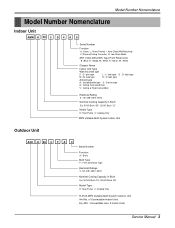
..., W : White Chassis Name Indoor Unit Type Wall mounted split D : D- look type L : L- look type M : M- look type G : G- of Connectable Indoor Units Ex) A3U : Connectable max. 2 Indoor Units Service Manual 3 look type N : N- look type Artcool type A : standard/wide type D : Deluxe type B : Ceiling Concealed Duct V : Ceiling & Floor(Convertible) Electrical Rating 3: 1Ø, 208~230V, 60Hz Nominal Cooling...
..., W : White Chassis Name Indoor Unit Type Wall mounted split D : D- look type L : L- look type M : M- look type G : G- of Connectable Indoor Units Ex) A3U : Connectable max. 2 Indoor Units Service Manual 3 look type N : N- look type Artcool type A : standard/wide type D : Deluxe type B : Ceiling Concealed Duct V : Ceiling & Floor(Convertible) Electrical Rating 3: 1Ø, 208~230V, 60Hz Nominal Cooling...
Service Manual
Page 5
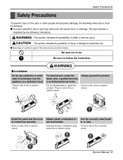
... install a dedicated cir- Safety Precautions Safety Precautions To prevent injury to the user or other people and property damage, the following indications. Service Manual 5 Be sure not to ignoring instruction will cause harm or damage. s Incorrect operation due to do. Be sure to properties only. For... work, contact the Always ground the product. WARNING This symbol indicates the possibility of injury or damage to follow the instruction. Use this manual are as shown below. There is risk of fire or electric shock. • There is risk of control box securely. er or ...
... install a dedicated cir- Safety Precautions Safety Precautions To prevent injury to the user or other people and property damage, the following indications. Service Manual 5 Be sure not to ignoring instruction will cause harm or damage. s Incorrect operation due to do. Be sure to properties only. For... work, contact the Always ground the product. WARNING This symbol indicates the possibility of injury or damage to follow the instruction. Use this manual are as shown below. There is risk of fire or electric shock. • There is risk of control box securely. er or ...
Service Manual
Page 7
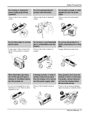
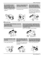
... of property damage, failure of fire and electric shock. Gasolin When flammable gas leaks, turn switches on or off or disconnect the power supply cable. Service Manual 7
... of property damage, failure of fire and electric shock. Gasolin When flammable gas leaks, turn switches on or off or disconnect the power supply cable. Service Manual 7
Service Manual
Page 9
..., etc. Do not use the product for special purposes, such as preserving foods, works of property. Use two or more people to clean. Wax Thinner Service Manual 9 Corrosion, particularly on the product. Use a soft cloth to lift and transport the product. They are very sharp! • It may cause a problem for long...
..., etc. Do not use the product for special purposes, such as preserving foods, works of property. Use two or more people to clean. Wax Thinner Service Manual 9 Corrosion, particularly on the product. Use a soft cloth to lift and transport the product. They are very sharp! • It may cause a problem for long...

Service Manual
Page 11
Dimensions Indoor Unit 1. Split Type Indoor H D W Dimensions 2. Art Cool Type Indoor Unit W D H Pipe Hole Hanger Hole Installation plate Fix Hole Dimension W H D Model mm mm mm Split Type S4 SE 9 kBtu/h 12 kBtu/h 840 895 270 282 153 165 ARTCOOL Type SP3 9 kBtu/h 12 kBtu/h 570 568 129 Service Manual 11
Dimensions Indoor Unit 1. Split Type Indoor H D W Dimensions 2. Art Cool Type Indoor Unit W D H Pipe Hole Hanger Hole Installation plate Fix Hole Dimension W H D Model mm mm mm Split Type S4 SE 9 kBtu/h 12 kBtu/h 840 895 270 282 153 165 ARTCOOL Type SP3 9 kBtu/h 12 kBtu/h 570 568 129 Service Manual 11
Service Manual
Page 13
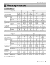
...) 9(19.84) 1/4 (6.35) 3/8 (9.52) 20 26.2*25.7*9.1(665*653*231) 237/534(239/539) Note : 1.5 See the page "Combination Table" 2. Service Manual 13 Used / Diameter Noise Level (Sound Press,1m) H/M/L Temperature controller Coil Tube Size (OD) Fins per inch No. Due to our policy of Rows & Column... EA/inch(mm) dBA inch(mm) l/h inch(mm) kg(lbs) inch(mm) inch(mm) mm inch(mm) 20/40ft(hi-c) Wall Mounted AMNC093D4A0(LMN090CE) AMNH093D4A0(LMN090HE) AMNC123DEA0(LMN120CE) AMNH123DEA0(LMN120HE) 2,267(2,637) 9,000 - 8.2(289) 18~30 15 DL-88430LGIF DC36 0.15 Cross Flow Fan 1/3.74(95) 31 / 29 / 22...
...) 9(19.84) 1/4 (6.35) 3/8 (9.52) 20 26.2*25.7*9.1(665*653*231) 237/534(239/539) Note : 1.5 See the page "Combination Table" 2. Service Manual 13 Used / Diameter Noise Level (Sound Press,1m) H/M/L Temperature controller Coil Tube Size (OD) Fins per inch No. Due to our policy of Rows & Column... EA/inch(mm) dBA inch(mm) l/h inch(mm) kg(lbs) inch(mm) inch(mm) mm inch(mm) 20/40ft(hi-c) Wall Mounted AMNC093D4A0(LMN090CE) AMNH093D4A0(LMN090HE) AMNC123DEA0(LMN120CE) AMNH123DEA0(LMN120HE) 2,267(2,637) 9,000 - 8.2(289) 18~30 15 DL-88430LGIF DC36 0.15 Cross Flow Fan 1/3.74(95) 31 / 29 / 22...
Service Manual
Page 15
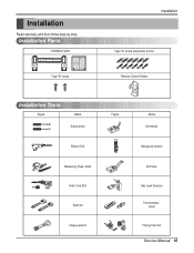
Installation Read carefully, and then follow step by step. Installation Parts Installation plate Type "B" screw Installation Type "A" screw and plastic anchor Remote Control Holder Installation Tools Figure Name Screw driver Electric Drill Measuring Tape, Knife Hole Core Drill Spanner Torque wrench Figure Name Ohmmeter Hexagonal wrench Ammeter Gas Leak Detector Thermometer, Level Flaring Tool Set Service Manual 15
Installation Read carefully, and then follow step by step. Installation Parts Installation plate Type "B" screw Installation Type "A" screw and plastic anchor Remote Control Holder Installation Tools Figure Name Screw driver Electric Drill Measuring Tape, Knife Hole Core Drill Spanner Torque wrench Figure Name Ohmmeter Hexagonal wrench Ammeter Gas Leak Detector Thermometer, Level Flaring Tool Set Service Manual 15
Service Manual
Page 17
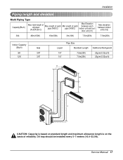
Service Manual 17 Installation Piping length and elevation Multi Piping Type Capacity(Btu/h) Max total length of all pipes (A+B/A+B+C) Max length of each pipe (A/B/C) Min length of ...
Service Manual 17 Installation Piping length and elevation Multi Piping Type Capacity(Btu/h) Max total length of all pipes (A+B/A+B+C) Max length of each pipe (A/B/C) Min length of ...
Service Manual
Page 19
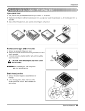
... hole of drainage. 2. After pull down this time panel front is separated 3. Pipe hole Adhesive Only one desiring direction Connecting part Drain hose rubber cap Service Manual 19 Remove the rubber stopple of desired direction of cover side. First, push the front panel backward and lift it up the cover side of...
... hole of drainage. 2. After pull down this time panel front is separated 3. Pipe hole Adhesive Only one desiring direction Connecting part Drain hose rubber cap Service Manual 19 Remove the rubber stopple of desired direction of cover side. First, push the front panel backward and lift it up the cover side of...
Service Manual
Page 21
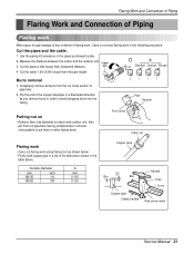
... purchased locally. 2. Outside diameter mm inch Ø6.35 1/4 Ø9.52 3/8 A mm 0~0.5 0~0.5 Copper tube Handle "A" Bar Bar Yoke Cone Copper pipe Clamp handle Red arrow mark Service Manual 21
... purchased locally. 2. Outside diameter mm inch Ø6.35 1/4 Ø9.52 3/8 A mm 0~0.5 0~0.5 Copper tube Handle "A" Bar Bar Yoke Cone Copper pipe Clamp handle Red arrow mark Service Manual 21

Service Manual
Page 23
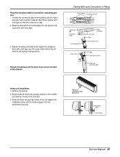
... unit pipe Vinyl tape (wide) Wrap with vinyl tape Connecting cable Pipe Vinyl tape(narrow) Pipe Wrap with vinyl tape Drain hose Vinyl tape(wide) Service Manual 23 Bind them with vinyl tape so that the hooks are properly seated on the installation plate by moving it left and right sides of...
... unit pipe Vinyl tape (wide) Wrap with vinyl tape Connecting cable Pipe Vinyl tape(narrow) Pipe Wrap with vinyl tape Drain hose Vinyl tape(wide) Service Manual 23 Bind them with vinyl tape so that the hooks are properly seated on the installation plate by moving it left and right sides of...
Service Manual
Page 25
... hooks are properly seated on the installation plate by wrapping them together with vinyl tape. 3. Piping for passage through piping hole Connecting cable Drain hose Service Manual 25 Bundle the piping and drain hose together by moving it left and right sides of the chassis.
... hooks are properly seated on the installation plate by wrapping them together with vinyl tape. 3. Piping for passage through piping hole Connecting cable Drain hose Service Manual 25 Bundle the piping and drain hose together by moving it left and right sides of the chassis.
Service Manual
Page 27
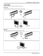
Flaring Work and Connection of clamp and unfold the tubing to downward slowly. For left may cause damage to left piping. Bad case • Following bending type from right to the tubing. Good case • Press on the upper side of Piping Installation Information. Follow the instruction below. Service Manual 27
Flaring Work and Connection of clamp and unfold the tubing to downward slowly. For left may cause damage to left piping. Bad case • Following bending type from right to the tubing. Good case • Press on the upper side of Piping Installation Information. Follow the instruction below. Service Manual 27
Service Manual
Page 29
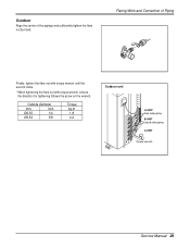
Outdoor Align the center of Piping Finally, tighten the flare nut with torque wrench until the wrench clicks. • When tightening the flare nut with torque wrench, ensure the direction for tightening follows the arrow on the wrench. Flaring Work and Connection of the pipings and sufficiently tighten the flare nut by hand. Outside diameter mm inch Ø6.35 1/4 Ø9.52 3/8 Torque kg.m 1.8 4.2 Outdoor unit A-UNIT Gas side piping B-UNIT Liquid side piping C-UNIT Torque wrench Service Manual 29
Outdoor Align the center of Piping Finally, tighten the flare nut with torque wrench until the wrench clicks. • When tightening the flare nut with torque wrench, ensure the direction for tightening follows the arrow on the wrench. Flaring Work and Connection of the pipings and sufficiently tighten the flare nut by hand. Outside diameter mm inch Ø6.35 1/4 Ø9.52 3/8 Torque kg.m 1.8 4.2 Outdoor unit A-UNIT Gas side piping B-UNIT Liquid side piping C-UNIT Torque wrench Service Manual 29
Service Manual
Page 31
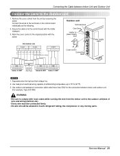
... 34 Terminal BLOCK Indoor A-UNIT L N Power Source 208/230V AC (High voltage) 12 34 Terminal BLOCK Indoor B-UNIT 12 34 Terminal BLOCK Indoor C-UNIT NOTICE : 1. Service Manual 31 Secure the cable onto the control board with the screw. Use heat-proof electrical wiring capable of wire and wiring method, etc). • Every...
... 34 Terminal BLOCK Indoor A-UNIT L N Power Source 208/230V AC (High voltage) 12 34 Terminal BLOCK Indoor B-UNIT 12 34 Terminal BLOCK Indoor C-UNIT NOTICE : 1. Service Manual 31 Secure the cable onto the control board with the screw. Use heat-proof electrical wiring capable of wire and wiring method, etc). • Every...
Service Manual
Page 33
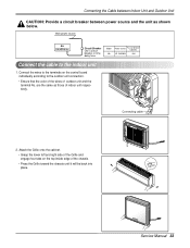
.... • Grasp the lower left and right side of the Grille and engage four tabs on the control board individually according to the indoor unit 1. Service Manual 33 Main power source Air Conditioner Circuit Breaker Use a circuit breaker or time delay fuse.
.... • Grasp the lower left and right side of the Grille and engage four tabs on the control board individually according to the indoor unit 1. Service Manual 33 Main power source Air Conditioner Circuit Breaker Use a circuit breaker or time delay fuse.
Service Manual
Page 35
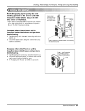
... parts. Seal a small opening around the pipings with gum type sealer. Secure the taped piping along the exterior wall using saddle or equivalent. Trap Trap Service Manual 35 Secure the tapped piping along the exterior wall. Checking the Drainage, Forming the Pipings and Long Pipe Setting Forming the piping Form the piping...
... parts. Seal a small opening around the pipings with gum type sealer. Secure the taped piping along the exterior wall using saddle or equivalent. Trap Trap Service Manual 35 Secure the tapped piping along the exterior wall. Checking the Drainage, Forming the Pipings and Long Pipe Setting Forming the piping Form the piping...
Service Manual
Page 37
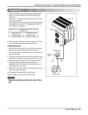
.... Required time for each indoor unit. or more Outdoor unit Indoor unit 2. Manifold valve Pressure gauge Lo Hi Open Close Vacuum pump Service Manual 37 Checking the Drainage, Forming the Pipings and Long Pipe Setting Evacuation 1. Connect the charge hose end described in the preceding steps to... the vacuum pump to release the pressure, then remove the hose. 4. Then, run the vacuum pump. With a service valve wrench, turn the valve stem of the manifold valve is longer than 10m (33 ft) If tubing length is open the valve. 3. ...
.... Required time for each indoor unit. or more Outdoor unit Indoor unit 2. Manifold valve Pressure gauge Lo Hi Open Close Vacuum pump Service Manual 37 Checking the Drainage, Forming the Pipings and Long Pipe Setting Evacuation 1. Connect the charge hose end described in the preceding steps to... the vacuum pump to release the pressure, then remove the hose. 4. Then, run the vacuum pump. With a service valve wrench, turn the valve stem of the manifold valve is longer than 10m (33 ft) If tubing length is open the valve. 3. ...


