

Service Manual
Page 2
... Disassembly ...49 Indoor Unit...49 Schematic Diagram...54 Electronic Control Device ...54 Wiring Diagram...58 Components Locations...59 Troubleshooting Guide ...64 Refrigeration Cycle Diagram ...64 Self-diagnosis Function ...65 Cycle Troubleshooting Guide...66 Electronic Parts Troubleshooting Guide 67 General Information...72 2-way, 3-way Valve ...78 Exploded View & Replacement Parts List 82 Indoor Unit...
... Disassembly ...49 Indoor Unit...49 Schematic Diagram...54 Electronic Control Device ...54 Wiring Diagram...58 Components Locations...59 Troubleshooting Guide ...64 Refrigeration Cycle Diagram ...64 Self-diagnosis Function ...65 Cycle Troubleshooting Guide...66 Electronic Parts Troubleshooting Guide 67 General Information...72 2-way, 3-way Valve ...78 Exploded View & Replacement Parts List 82 Indoor Unit...
Service Manual
Page 64
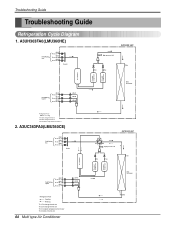
... C Ø6.35 Room B Ø6.35 Room A LEV-C LEV-B LEV-A Heat Exchanger Refrigerant Flow Cooling Th1: Discharge thermistor Th2: Discharge thermistor Th3: Outdoor temperature thermistor 2. Troubleshooting Guide Troubleshooting Guide Refrigeration Cycle Diagram 1. A3UC363FA0(LMU360CE) Field Piping Gas Ø9.52 Room C Ø9.52 Room B Ø9.52 Room A Header OUTDOOR UNIT High pressure S/W Th3 Th1...
... C Ø6.35 Room B Ø6.35 Room A LEV-C LEV-B LEV-A Heat Exchanger Refrigerant Flow Cooling Th1: Discharge thermistor Th2: Discharge thermistor Th3: Outdoor temperature thermistor 2. Troubleshooting Guide Troubleshooting Guide Refrigeration Cycle Diagram 1. A3UC363FA0(LMU360CE) Field Piping Gas Ø9.52 Room C Ø9.52 Room B Ø9.52 Room A Header OUTDOOR UNIT High pressure S/W Th3 Th1...
Service Manual
Page 65
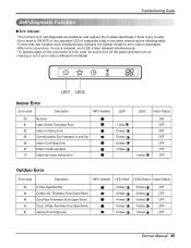
...(Open/Short) 51 Capcity Error(High/Low) 3 times 3 times OFF 4 times 4 times OFF 4 times 5 times OFF 4 times 7 times OFF 5 times 1 times OFF Service Manual 65 Troubleshooting Guide Self-diagnosis Function s Error Indicator • The function is to self-diagnoisis airconditioner and express the troubles identifically if there is any trouble. •...
...(Open/Short) 51 Capcity Error(High/Low) 3 times 3 times OFF 4 times 4 times OFF 4 times 5 times OFF 4 times 7 times OFF 5 times 1 times OFF Service Manual 65 Troubleshooting Guide Self-diagnosis Function s Error Indicator • The function is to self-diagnoisis airconditioner and express the troubles identifically if there is any trouble. •...

Service Manual
Page 66
... type Air Conditioner The suction pressure is usually 4.5~6.0 kg/cm2G at the beginning of refrigerant(Leakage) Clogging Description Current is smaller. Check refrigeration cycle. Troubleshooting Guide Cycle Troubleshooting Guide Trouble analysis 1. The temperature can be measured by attaching the thermometer to the low pressure tubing and wrap it with the normal value...
... type Air Conditioner The suction pressure is usually 4.5~6.0 kg/cm2G at the beginning of refrigerant(Leakage) Clogging Description Current is smaller. Check refrigeration cycle. Troubleshooting Guide Cycle Troubleshooting Guide Trouble analysis 1. The temperature can be measured by attaching the thermometer to the low pressure tubing and wrap it with the normal value...
Service Manual
Page 67
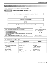
...Specification 1) AC230V ± 30V : Check the rated voltage 2) 15V ± 1.5V 3) DC12V 4) DC5V 5) The voltage of power trans- Electronic Parts Troubleshooting Guide ❇ Refer to the unit. • The connecting method of Indoor/Outdoor connecting cable (each color) • The P.W.B. Trouble 1 The Product ...29 : DC4.5V↑ Remedy 1) Replace power transfomer. 2) Replace power transfomer. 3) Replace IC01D. 4) Replace IC02D. 5) Replace IC01A. Troubleshooting Guide Turn off the main power and wait until LED on the main power again. NO Check the voltage of power(AC208V/AC230V, 60Hz)....
...Specification 1) AC230V ± 30V : Check the rated voltage 2) 15V ± 1.5V 3) DC12V 4) DC5V 5) The voltage of power trans- Electronic Parts Troubleshooting Guide ❇ Refer to the unit. • The connecting method of Indoor/Outdoor connecting cable (each color) • The P.W.B. Trouble 1 The Product ...29 : DC4.5V↑ Remedy 1) Replace power transfomer. 2) Replace power transfomer. 3) Replace IC01D. 4) Replace IC02D. 5) Replace IC01A. Troubleshooting Guide Turn off the main power and wait until LED on the main power again. NO Check the voltage of power(AC208V/AC230V, 60Hz)....

Service Manual
Page 68
... a low speed. Check DISP PWB Ass'y -Voltage between CN1 DC +5V Check the Display PWB Ass'y • Check receiver ass'y 68 Multi type Air Conditioner Troubleshooting Guide Trouble 2 Product doesn't operate with the remote controller. While the compressor has been stopped, the compressor does not operate owing to operate temperature regulating...
... a low speed. Check DISP PWB Ass'y -Voltage between CN1 DC +5V Check the Display PWB Ass'y • Check receiver ass'y 68 Multi type Air Conditioner Troubleshooting Guide Trouble 2 Product doesn't operate with the remote controller. While the compressor has been stopped, the compressor does not operate owing to operate temperature regulating...
Service Manual
Page 69
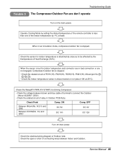
... to connect the Outdoor (About AC208V / 230V). • Check the related circuit of Outdoor side. ON DC 5V DC 1V↓ Comp. Service Manual 69 Troubleshooting Guide Trouble 3 The Compressor/Outdoor Fan are not engaged, Compressor/Outdoor fan is stopped. • Check the related circuit of R01H(1K), R02H(1K), R03H...
... to connect the Outdoor (About AC208V / 230V). • Check the related circuit of Outdoor side. ON DC 5V DC 1V↓ Comp. Service Manual 69 Troubleshooting Guide Trouble 3 The Compressor/Outdoor Fan are not engaged, Compressor/Outdoor fan is stopped. • Check the related circuit of R01H(1K), R02H(1K), R03H...
Service Manual
Page 70
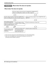
... patterns and the conditions of Indoor Fan. Check the interference of outdoor unit PWB Assy's. Indoor Fan is turned on) 70 Multi type Air Conditioner Troubleshooting Guide Trouble 4 When indoor Fan does not operate. Check the connecting condition and disconnection of Indoor unit PWB Ass'y. When indoor Fan does not operate...
... patterns and the conditions of Indoor Fan. Check the interference of outdoor unit PWB Assy's. Indoor Fan is turned on) 70 Multi type Air Conditioner Troubleshooting Guide Trouble 4 When indoor Fan does not operate. Check the connecting condition and disconnection of Indoor unit PWB Ass'y. When indoor Fan does not operate...
Service Manual
Page 71
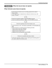
... - Between 12 , 13 , 14 , 15 of CN-UP/DOWN and GND. • Confirm that are catching and interfering parts in the rotation radial of MICOM - Troubleshooting Guide Trouble 5 When the louver does not operate. Between 60 , 61 , 62 and 63 of the Vertical Louver Service Manual 71 Between 1 , 2 , 3 , 4 and 5 of CN...
... - Between 12 , 13 , 14 , 15 of CN-UP/DOWN and GND. • Confirm that are catching and interfering parts in the rotation radial of MICOM - Troubleshooting Guide Trouble 5 When the louver does not operate. Between 60 , 61 , 62 and 63 of the Vertical Louver Service Manual 71 Between 1 , 2 , 3 , 4 and 5 of CN...

Service Manual
Page 72
Troubleshooting Guide Error Code s Trouble Shooting Error code Title 01 Indoor air sensor 02 Indoor inlet pipe sensor 06 Indoor outlet pipe sensor Cause of each ...
Troubleshooting Guide Error Code s Trouble Shooting Error code Title 01 Indoor air sensor 02 Indoor inlet pipe sensor 06 Indoor outlet pipe sensor Cause of each ...
Service Manual
Page 73
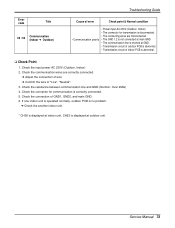
... GND. 6. Check the resistance between communication line and GND.(Normal : Over 2MΩ) 4. Service Manual 73 Error code Title 05 / 53 Communication (Indoor ➔ Outdoor) Troubleshooting Guide Cause of error Check point & Normal condition • Power input AC 230V.(Outdoor, Indoor) • The connector for communication is correctly connected. 5. Check the...
... GND. 6. Check the resistance between communication line and GND.(Normal : Over 2MΩ) 4. Service Manual 73 Error code Title 05 / 53 Communication (Indoor ➔ Outdoor) Troubleshooting Guide Cause of error Check point & Normal condition • Power input AC 230V.(Outdoor, Indoor) • The connector for communication is correctly connected. 5. Check the...
Service Manual
Page 74
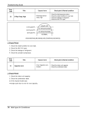
... 51 Capacitor error Cause of refrigerent. 4. high Check point & Normal condition • Check the discharge pipe sensor. • Check the install condition for over load. 2. Troubleshooting Guide Error code Title 33 D-Pipe Temp. Check the indoor unit capacity. 2. High Cause of refrigerent. • Check the SVC V/V open . 3.
... 51 Capacitor error Cause of refrigerent. 4. high Check point & Normal condition • Check the discharge pipe sensor. • Check the install condition for over load. 2. Troubleshooting Guide Error code Title 33 D-Pipe Temp. Check the indoor unit capacity. 2. High Cause of refrigerent. • Check the SVC V/V open . 3.

Service Manual
Page 75
Error code Title 44 Outdoor air sensor 45 Condensor pipe sensor 47 D-Pipe sensor Troubleshooting Guide Cause of each sensor.(Unplugged) 2. Estimate the voltage of error • Open / Short • Soldered poorly • Internal circuit error • Open / Short • ...
Error code Title 44 Outdoor air sensor 45 Condensor pipe sensor 47 D-Pipe sensor Troubleshooting Guide Cause of each sensor.(Unplugged) 2. Estimate the voltage of error • Open / Short • Soldered poorly • Internal circuit error • Open / Short • ...
