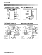
Service Manual
Page 2
... Operation ...40 Function of control...40 Function of Indoor Unit ...45 Function of Outdoor Unit ...47 Remote Control Operation ...48 Disassembly ...49 Indoor Unit...49 Schematic Diagram...54 Electronic Control Device ...54 Wiring Diagram...58 Components Locations...59 Troubleshooting Guide ...64 Refrigeration Cycle Diagram ...64 Self-diagnosis Function ...65 Cycle Troubleshooting...
Service Manual
Page 55
Service Manual 55 Schematic Diagram STEPPING MOTOR SUB PCB ASM STEPPING MOTOR STEPPING MOTOR LED2 SLEEP LED3 TIMER LED4 DEFROST LED1 ON/OFF 4(f) a 11 3(a) 22 b f 1(g) 33 g 9(b) 4 4 6(d) c e 55 7(e) 66 8(c) d 77 ...
Service Manual
Page 58
A3UC363FA0(LMU360CE) 58 Multi type Air Conditioner Outdoor Unit 1. Schematic Diagram Wiring Diagram 1. Art Cool Type Indoor Unit 3. Room Type Indoor Unit -S4/SE chassis 2. A3UH363FA0(LMU360HE) 2.
Service Manual
Page 59
Indoor Unit MAIN P.C.B ASM 1) Split Type • TOP VIEW Schematic Diagram PCB :6870A90409B ASSY :6871A20771 6871A20782 • BOTTOM VIEW Service Manual 59 Components Locations 1.
Service Manual
Page 67
... 67 NO Check the voltage of power(AC208V/AC230V, 60Hz). • The voltage of main power. • The voltage applied to electronic contorol device drawing & schematic diagram. Ass'y Procedure 1) The input voltage of micom pin 29 : DC4.5V↑ Remedy 1) Replace power transfomer. 2) Replace power transfomer. 3) Replace IC01D. 4) Replace IC02D. 5) Replace...