

Service Manual
Page 2
... Model Number Nomenclature ...3 Symbols Used in this Manual ...4 Safety Precautions...5 Dimensions...11 Indoor Unit...11 Outdoor Unit ...12 Product Specifications ...13 Installation ...15 Installation Parts...15 Installation Tools...15 Select the best location ...16 Piping length and elevation ...17 Fixing Installation Plate(Standart Type 18 Preparing work for Installation (Artcool Type Only 19 Flaring Work and...
... Model Number Nomenclature ...3 Symbols Used in this Manual ...4 Safety Precautions...5 Dimensions...11 Indoor Unit...11 Outdoor Unit ...12 Product Specifications ...13 Installation ...15 Installation Parts...15 Installation Tools...15 Select the best location ...16 Piping length and elevation ...17 Fixing Installation Plate(Standart Type 18 Preparing work for Installation (Artcool Type Only 19 Flaring Work and...
Service Manual
Page 5
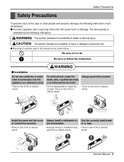
... or electric shock shock. s Meanings of symbols used in this dealer, seller, a qualified electrician, appliance on a dedicated circuit. Install the panel and the cover Always install a dedicated cir- er or fuse. • There is risk of fire or electric shock. • Improper wiring or... Do not disassemble or repair the product. cuit and breaker. Service Manual 5 There is risk of fire or electric shock. • There is risk of fire or electric shock. Be sure to properties only. WARNING s Installation Do not use a defective or under- For electrical work, contact the...
... or electric shock shock. s Meanings of symbols used in this dealer, seller, a qualified electrician, appliance on a dedicated circuit. Install the panel and the cover Always install a dedicated cir- er or fuse. • There is risk of fire or electric shock. • Improper wiring or... Do not disassemble or repair the product. cuit and breaker. Service Manual 5 There is risk of fire or electric shock. • There is risk of fire or electric shock. Be sure to properties only. WARNING s Installation Do not use a defective or under- For electrical work, contact the...
Service Manual
Page 9
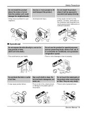
... preserving foods, works of property. It is a consumer air conditioner, not a precision refrigeration system. • There is risk of air flow. Wax Thinner Service Manual 9 Do not install the product where it will be exposed to sea wind (salt spray) directly. • Avoid personal injury. • It may cause product failure. •...
... preserving foods, works of property. It is a consumer air conditioner, not a precision refrigeration system. • There is risk of air flow. Wax Thinner Service Manual 9 Do not install the product where it will be exposed to sea wind (salt spray) directly. • Avoid personal injury. • It may cause product failure. •...

Service Manual
Page 11
Art Cool Type Indoor Unit W D H Pipe Hole Hanger Hole Installation plate Fix Hole Dimension W H D Model mm mm mm Split Type S4 SE 9 kBtu/h 12 kBtu/h 840 895 270 282 153 165 ARTCOOL Type SP3 9 kBtu/h 12 kBtu/h 570 568 129 Service Manual 11 Dimensions Indoor Unit 1. Split Type Indoor H D W Dimensions 2.
Art Cool Type Indoor Unit W D H Pipe Hole Hanger Hole Installation plate Fix Hole Dimension W H D Model mm mm mm Split Type S4 SE 9 kBtu/h 12 kBtu/h 840 895 270 282 153 165 ARTCOOL Type SP3 9 kBtu/h 12 kBtu/h 570 568 129 Service Manual 11 Dimensions Indoor Unit 1. Split Type Indoor H D W Dimensions 2.
Service Manual
Page 15
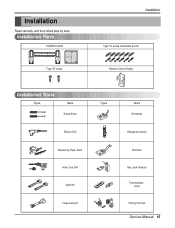
Installation Read carefully, and then follow step by step. Installation Parts Installation plate Type "B" screw Installation Type "A" screw and plastic anchor Remote Control Holder Installation Tools Figure Name Screw driver Electric Drill Measuring Tape, Knife Hole Core Drill Spanner Torque wrench Figure Name Ohmmeter Hexagonal wrench Ammeter Gas Leak Detector Thermometer, Level Flaring Tool Set Service Manual 15
Installation Read carefully, and then follow step by step. Installation Parts Installation plate Type "B" screw Installation Type "A" screw and plastic anchor Remote Control Holder Installation Tools Figure Name Screw driver Electric Drill Measuring Tape, Knife Hole Core Drill Spanner Torque wrench Figure Name Ohmmeter Hexagonal wrench Ammeter Gas Leak Detector Thermometer, Level Flaring Tool Set Service Manual 15
Service Manual
Page 17
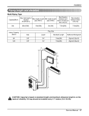
Installation Piping length and elevation Multi Piping Type Capacity(Btu/h) Max total length of all pipes (A+B/A+B+C) Max length of each pipe (A/B/C) Min length of each pipe (A/B/C) .../m(0.32oz/ft) A h2 B h2 h1 C h1 h1 CAUTION: Capacity is based on standard length and maximum allowance length is on the basis of reliability. Service Manual 17 Oil trap should be installed every 5~7 meters (16.4~23.0ft).
Installation Piping length and elevation Multi Piping Type Capacity(Btu/h) Max total length of all pipes (A+B/A+B+C) Max length of each pipe (A/B/C) Min length of each pipe (A/B/C) .../m(0.32oz/ft) A h2 B h2 h1 C h1 h1 CAUTION: Capacity is based on standard length and maximum allowance length is on the basis of reliability. Service Manual 17 Oil trap should be installed every 5~7 meters (16.4~23.0ft).
Service Manual
Page 19
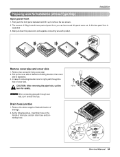
... Remove cover pipe and cover side 1. Pipe hole Adhesive Only one desiring direction Connecting part Drain hose rubber cap Service Manual 19 CAUTION: After removing the pipe hole, cut the burr for Installation (Artcool Type Only) Open panel front 1. Remove two screws(for fixing cover pipe) 2. Drain hose junction 1. After pull down...
... Remove cover pipe and cover side 1. Pipe hole Adhesive Only one desiring direction Connecting part Drain hose rubber cap Service Manual 19 CAUTION: After removing the pipe hole, cut the burr for Installation (Artcool Type Only) Open panel front 1. Remove two screws(for fixing cover pipe) 2. Drain hose junction 1. After pull down...
Service Manual
Page 20
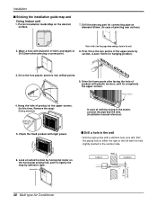
... lower parts after facing the hole of product with the hole slightly slanted to No. 5 on this time, Remove the map) (Falling attention) INSTALLATION GUIDE MAP Hanger hole (Rear side of product at suited horizon by horizontal meter on the desired surface. Check the fixed product with a ø50mm... MAP Refer to the outdoor side. 6. First, Drive the two points of nothing wrong in the matter, connect the pipe and the wire. (Installation manual reference) s Drill a hole in the wall. 8. Hang the hole of product) 5. Look at the upper screws. (In this page when making a hole in ...
... lower parts after facing the hole of product with the hole slightly slanted to No. 5 on this time, Remove the map) (Falling attention) INSTALLATION GUIDE MAP Hanger hole (Rear side of product at suited horizon by horizontal meter on the desired surface. Check the fixed product with a ø50mm... MAP Refer to the outdoor side. 6. First, Drive the two points of nothing wrong in the matter, connect the pipe and the wire. (Installation manual reference) s Drill a hole in the wall. 8. Hang the hole of product) 5. Look at the upper screws. (In this page when making a hole in ...

Service Manual
Page 23
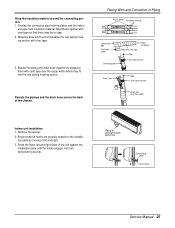
... Pipe Vinyl tape(narrow) Pipe Wrap with vinyl tape for enough to drain pipe. 1. When extending the drain hose at the indoor unit, install the drain pipe. Overlap the connection pipe insulation material and the indoor unit pipe insulation material. Flaring Work and Connection of the...onto the upper portion of the installation plate.(Engage the two hooks of the rear top of the unit against the installation plate until the hooks engage into the rear piping housing section. Press the lower left and right. Bind them with vinyl tape Drain hose Vinyl tape(wide) Service Manual 23
... Pipe Vinyl tape(narrow) Pipe Wrap with vinyl tape for enough to drain pipe. 1. When extending the drain hose at the indoor unit, install the drain pipe. Overlap the connection pipe insulation material and the indoor unit pipe insulation material. Flaring Work and Connection of the...onto the upper portion of the installation plate.(Engage the two hooks of the rear top of the unit against the installation plate until the hooks engage into the rear piping housing section. Press the lower left and right. Bind them with vinyl tape Drain hose Vinyl tape(wide) Service Manual 23
Service Manual
Page 25
...housing section with vinyl tape so that the hooks are properly seated on the installation plate by wrapping them together with vinyl tape. 3. Piping for passage through piping hole Connecting cable Drain hose Service Manual 25 Reroute the pipings and the drain hose across the back of the ...unit against the installation plate until the hooks engage into the rear piping housing section. Press the lower left ...
...housing section with vinyl tape so that the hooks are properly seated on the installation plate by wrapping them together with vinyl tape. 3. Piping for passage through piping hole Connecting cable Drain hose Service Manual 25 Reroute the pipings and the drain hose across the back of the ...unit against the installation plate until the hooks engage into the rear piping housing section. Press the lower left ...
Service Manual
Page 27
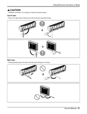
Flaring Work and Connection of clamp and unfold the tubing to the tubing. Bad case • Following bending type from right to left piping. Follow the instruction below. Service Manual 27 Good case • Press on the upper side of Piping Installation Information. For left may cause damage to downward slowly.
Flaring Work and Connection of clamp and unfold the tubing to the tubing. Bad case • Following bending type from right to left piping. Follow the instruction below. Service Manual 27 Good case • Press on the upper side of Piping Installation Information. For left may cause damage to downward slowly.
Service Manual
Page 35
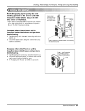
Taping Drain hose Plastic band Pipings Connecting cable Power supply cord • Trap is installed above the ground. Tape the piping and connecting cable from down to connect an additional drain ...the Pipings and Long Pipe Setting Forming the piping Form the piping by saddle or equivalent. In cases where the outdoor unit is installed below the indoor unit perform the following . 1. Seal a small opening around the pipings with two kinds of vinyl tape. ... is required to prevent water from down to prevent water entering the room. 3. Trap Trap Service Manual 35
Taping Drain hose Plastic band Pipings Connecting cable Power supply cord • Trap is installed above the ground. Tape the piping and connecting cable from down to connect an additional drain ...the Pipings and Long Pipe Setting Forming the piping Form the piping by saddle or equivalent. In cases where the outdoor unit is installed below the indoor unit perform the following . 1. Seal a small opening around the pipings with two kinds of vinyl tape. ... is required to prevent water from down to prevent water entering the room. 3. Trap Trap Service Manual 35
Service Manual
Page 39
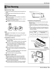
... 35°C (95°F) 8.5~9.5kg/cm2G(120~135 P.S.I.G.) Discharge air Intake temperature Discharge air Discharge temperature Intake temperature Discharge temperature Service Manual 39 Measure the temperature of the intake and discharge of the gas side service valve. The pressure of air. 3. Check that the... 90% of battery are fully open. 1) Prepare remote controller Remove the battery cover by pushing it leads to be operated. s When installing on a concrete or rigid mount. Check that all tubing and wiring have been properly connected. 2. s Carry out the test run more...
... 35°C (95°F) 8.5~9.5kg/cm2G(120~135 P.S.I.G.) Discharge air Intake temperature Discharge air Discharge temperature Intake temperature Discharge temperature Service Manual 39 Measure the temperature of the intake and discharge of the gas side service valve. The pressure of air. 3. Check that the... 90% of battery are fully open. 1) Prepare remote controller Remove the battery cover by pushing it leads to be operated. s When installing on a concrete or rigid mount. Check that all tubing and wiring have been properly connected. 2. s Carry out the test run more...
Service Manual
Page 81
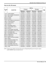
... chassis) Exploded View & Replacement Parts List LOCATION No. SE chassis AMNH093D4A0 AMNC093D4A0 AMNH123DEA0 AMNC123DEA0 (LMN090HE) (LMN090CE) (LMN120HE) (LMN120CE) SVC CODE 131410 CHASSIS ASSEMBLY 3141A20019C 3141A20019C 3141A20034A 3141A20034A R ...DRAIN 5251A20011B 5251A20011B 5251A20011G 5251A20011G R 359011 FAN ASSEMBLY,CROSS FLOW 5901A20017F 5901A20017F 5901A20017H 5901A20017H R 733010 PLATE ASSEMBLY,INSTALLATION 3301A20020C 3301A20020C 3301A20020A 3301A20020A R 135500 COVER 3550A30262A 3550A30262A 3550A30315A 3550A30315A R NOTE) *Please ensure GCSC since these ...
... chassis) Exploded View & Replacement Parts List LOCATION No. SE chassis AMNH093D4A0 AMNC093D4A0 AMNH123DEA0 AMNC123DEA0 (LMN090HE) (LMN090CE) (LMN120HE) (LMN120CE) SVC CODE 131410 CHASSIS ASSEMBLY 3141A20019C 3141A20019C 3141A20034A 3141A20034A R ...DRAIN 5251A20011B 5251A20011B 5251A20011G 5251A20011G R 359011 FAN ASSEMBLY,CROSS FLOW 5901A20017F 5901A20017F 5901A20017H 5901A20017H R 733010 PLATE ASSEMBLY,INSTALLATION 3301A20020C 3301A20020C 3301A20020A 3301A20020A R 135500 COVER 3550A30262A 3550A30262A 3550A30315A 3550A30315A R NOTE) *Please ensure GCSC since these ...


