Service Manual
Page 1
REFRIGERATOR SERVICE MANUAL CAUTION BEFORE SERVICING THE UNIT, READ THE SAFETY PRECAUTIONS IN THIS MANUAL. MODELS: LDC24370ST /00 LDC24370SW /00 LBC24360ST / 00 LBC24360SW /00
REFRIGERATOR SERVICE MANUAL CAUTION BEFORE SERVICING THE UNIT, READ THE SAFETY PRECAUTIONS IN THIS MANUAL. MODELS: LDC24370ST /00 LDC24370SW /00 LBC24360ST / 00 LBC24360SW /00
Service Manual
Page 2
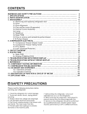
... injuries from spiling on to remove and reinstall de pullout drawer 9 3-10 Pullout Drawer 11 4. PARTS IDENTIFICATION 4 3. COMPRESSOR ELECTRICAL 12 4-1 Compressor Freezer Drawer model 12 4-2 Compressor Freezer Swing model 13 4-3 PTC-Starter 13 4-4 OLP (Overload Protector 14 5. COMPONENT TESTING INFORMATION 39 11. Always check line voltage and amperage. 4. COMPRESSOR TROUBLESHOOTING 43 12...
... injuries from spiling on to remove and reinstall de pullout drawer 9 3-10 Pullout Drawer 11 4. PARTS IDENTIFICATION 4 3. COMPRESSOR ELECTRICAL 12 4-1 Compressor Freezer Drawer model 12 4-2 Compressor Freezer Swing model 13 4-3 PTC-Starter 13 4-4 OLP (Overload Protector 14 5. COMPONENT TESTING INFORMATION 39 11. Always check line voltage and amperage. 4. COMPRESSOR TROUBLESHOOTING 43 12...
Service Manual
Page 3
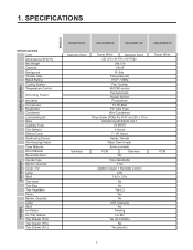
SPECIFICATIONS GENERAL FEATURES MODELS FREEZER REFRIGERATOR SPECIFICATIONS Color Dimensions (W*D*H) Net Weight Capacity Refrigerant Climate class Rated Rating Cooling System Temperature Control Defrosting System Insulation Compressor Evaporator... meat Tray Egg Tray Vegetable Pantry Basket, Quantity Lamp Shelf Ice Maker Ice Tray & Bank Tray Drawer (F/U) Tray Drawer (F/C) Tray Drawer (F/L) LDC24370ST /00 LDC24370SW /00 LBC24360ST / 00 LBC24360SW /00 Stainless Steel Stainless Super White Stainless Steel (32 3/4 x 34 7/8 x 69 7/8)in 248.5 lb 24cuft R134a Temperate (N) 115V~ / 60Hz ...
SPECIFICATIONS GENERAL FEATURES MODELS FREEZER REFRIGERATOR SPECIFICATIONS Color Dimensions (W*D*H) Net Weight Capacity Refrigerant Climate class Rated Rating Cooling System Temperature Control Defrosting System Insulation Compressor Evaporator... meat Tray Egg Tray Vegetable Pantry Basket, Quantity Lamp Shelf Ice Maker Ice Tray & Bank Tray Drawer (F/U) Tray Drawer (F/C) Tray Drawer (F/L) LDC24370ST /00 LDC24370SW /00 LBC24360ST / 00 LBC24360SW /00 Stainless Steel Stainless Super White Stainless Steel (32 3/4 x 34 7/8 x 69 7/8)in 248.5 lb 24cuft R134a Temperate (N) 115V~ / 60Hz ...

Service Manual
Page 8
Unplug refrigerator power cord form outlet. 2. Remove the upper and lower Caps by using a flat screwdriver, and remove 2 screws. (Figure 3) 2. If necessary, remove top shelf or shelves. 3-6-1 Refrigerator Compartment Lamp 1) Unplug refrigerator power cord from connector. 4) Replace the LED assembly. 3-8 MAIN PWB 1) Loosen 3 screws on the PWB cover. Remove screw with driver. 3. Disconnect the lead wire on the bottom position. 3) Remove the LED assembly from electric outlet. 2) Put flat screwdriver into service hole and remove cover of removal. 8 Figure 3 3-6-2 Freezer ...
Unplug refrigerator power cord form outlet. 2. Remove the upper and lower Caps by using a flat screwdriver, and remove 2 screws. (Figure 3) 2. If necessary, remove top shelf or shelves. 3-6-1 Refrigerator Compartment Lamp 1) Unplug refrigerator power cord from connector. 4) Replace the LED assembly. 3-8 MAIN PWB 1) Loosen 3 screws on the PWB cover. Remove screw with driver. 3. Disconnect the lead wire on the bottom position. 3) Remove the LED assembly from electric outlet. 2) Put flat screwdriver into service hole and remove cover of removal. 8 Figure 3 3-6-2 Freezer ...
Service Manual
Page 12
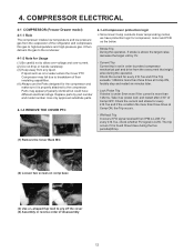
... not drop or handle carelessly. (3) Keep away from IPM is above the target value, decrease the target volt by part number and model number. Use only approved substitute parts. 4-1-3 REMOVE THE COVER PTC 4-1-4 Compressor protection logic Since linear Comp conducts linear reciprocating motion, we... if the Trip exceeds 1.86Arms more than three times at Comp ON, the Trip occurs. - COMPRESSOR ELECTRICAL 4-1 COMPRESSOR (Freezer Drawer model) 4-1-1 Role The compressor intakes low temperature and low pressure gas from the evaporator of their insulating capabilities. (4) Always use the Parts ...
... not drop or handle carelessly. (3) Keep away from IPM is above the target value, decrease the target volt by part number and model number. Use only approved substitute parts. 4-1-3 REMOVE THE COVER PTC 4-1-4 Compressor protection logic Since linear Comp conducts linear reciprocating motion, we... if the Trip exceeds 1.86Arms more than three times at Comp ON, the Trip occurs. - COMPRESSOR ELECTRICAL 4-1 COMPRESSOR (Freezer Drawer model) 4-1-1 Role The compressor intakes low temperature and low pressure gas from the evaporator of their insulating capabilities. (4) Always use the Parts ...
Service Manual
Page 13
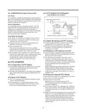
...the compressor can cause damage to the compressor and result in your product. (4) Keep Compressor dry. Replace parts by part number and model number. Dust, humidity, and solder flux contaminate the cylinder and may result. (3) Use proper electric components appropriate to equalize before the... flow only to allow over-voltage and over-current. (2) If compressor is , the higher the resistance value. 4-2 COMPRESSOR (Freezer Swing model) 4-2-1 Role The compressor intakes low temperature and low pressure gas from any liquid. Using an incorrect part could result in damage to the...
...the compressor can cause damage to the compressor and result in your product. (4) Keep Compressor dry. Replace parts by part number and model number. Dust, humidity, and solder flux contaminate the cylinder and may result. (3) Use proper electric components appropriate to equalize before the... flow only to allow over-voltage and over-current. (2) If compressor is , the higher the resistance value. 4-2 COMPRESSOR (Freezer Swing model) 4-2-1 Role The compressor intakes low temperature and low pressure gas from any liquid. Using an incorrect part could result in damage to the...
Service Manual
Page 19
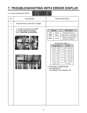
Check resistance between wires Blue/White to Blue/White. For example, 23㏀ indicates -4°F. 19 Result 0Ω Short OFF Open Other Normal SVC Action Change the sensor Replace the refrigerator Check the Temp and resistance (Table-1) Temperature Result -22°F / -30°C 40.5 ~ 38.5 ㏀ -13°F / -25°C 30.5 ~ 28.5 ㏀ -4°F / -20°C 23 ~ 21.5 ㏀ 5°F / -15°C 17.5 ~ 16.5 ㏀ 14°F / -10°C 13.5 ~ 12.5 ㏀ 23°F / -5°C 10.5 ~ 9.5 ㏀ 32°F / 0°C 8 ~7.5 ㏀ ※ The ...
Check resistance between wires Blue/White to Blue/White. For example, 23㏀ indicates -4°F. 19 Result 0Ω Short OFF Open Other Normal SVC Action Change the sensor Replace the refrigerator Check the Temp and resistance (Table-1) Temperature Result -22°F / -30°C 40.5 ~ 38.5 ㏀ -13°F / -25°C 30.5 ~ 28.5 ㏀ -4°F / -20°C 23 ~ 21.5 ㏀ 5°F / -15°C 17.5 ~ 16.5 ㏀ 14°F / -10°C 13.5 ~ 12.5 ㏀ 23°F / -5°C 10.5 ~ 9.5 ㏀ 32°F / 0°C 8 ~7.5 ㏀ ※ The ...
Service Manual
Page 20
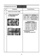
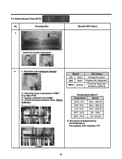
Unplug connector from CON7. 2-. Result & SVC Action Result 0Ω Short OFF Open Other Normal SVC Action Change the sensor Replace the refrigerator Check the Temp and resistance (Table-2) Temperature Result 23°F / -5°C 38.5 ~ 36.5 ㏀ 32°F / 0°C 30.5 ~ 29.5 ㏀ 41°F / 5°C 24.5 ~ 23.5 ㏀ 50°F / 10°C 20 ~ 19 ㏀ 59°F / 15°C 16 ~15.5 ㏀ ※ The sensor is determined by the temperature. 7-2 Refrigerator Sensor Error (rS E) No Checking flow 1 Check for loose connection in CON7. 2 1-. For...
Unplug connector from CON7. 2-. Result & SVC Action Result 0Ω Short OFF Open Other Normal SVC Action Change the sensor Replace the refrigerator Check the Temp and resistance (Table-2) Temperature Result 23°F / -5°C 38.5 ~ 36.5 ㏀ 32°F / 0°C 30.5 ~ 29.5 ㏀ 41°F / 5°C 24.5 ~ 23.5 ㏀ 50°F / 10°C 20 ~ 19 ㏀ 59°F / 15°C 16 ~15.5 ㏀ ※ The sensor is determined by the temperature. 7-2 Refrigerator Sensor Error (rS E) No Checking flow 1 Check for loose connection in CON7. 2 1-. For...
Service Manual
Page 21
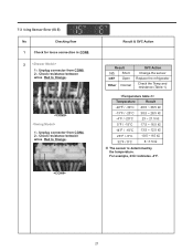
Unplug connector from CON4. 2-. Unplug connector from CON8. 2-. For example, 23㏀ indicates -4°F. 21 7-3 Icing Sensor Error (IS E) No Checking flow 1 Check for loose connection in CON8. 2 1-. Check resistance between wires Red to Orange. Check resistance between wires Red to Orange. 1-. Result & SVC Action Result 0Ω Short OFF Open Other Normal SVC Action Change the sensor Replace the refrigerator Check the Temp and resistance (Table-1) Temperature Result -22°F / -30°C 40.5 ~ 38.5 ㏀ -13°F / -25°C 30.5 ~ 28.5 &#...
Unplug connector from CON4. 2-. Unplug connector from CON8. 2-. For example, 23㏀ indicates -4°F. 21 7-3 Icing Sensor Error (IS E) No Checking flow 1 Check for loose connection in CON8. 2 1-. Check resistance between wires Red to Orange. Check resistance between wires Red to Orange. 1-. Result & SVC Action Result 0Ω Short OFF Open Other Normal SVC Action Change the sensor Replace the refrigerator Check the Temp and resistance (Table-1) Temperature Result -22°F / -30°C 40.5 ~ 38.5 ㏀ -13°F / -25°C 30.5 ~ 28.5 &#...
Service Manual
Page 22
7-4 Defrost Sensor Error (dS E) No Checking flow 1 (1) (2) Result & SVC Action Check for loose connection in CON7 from CON7. 4-. Check the wires Orange to Brown. Unplug connector from Main PCB. 3-. Check resistance between wires Brown to Orange. For example, 23㏀ indicates -4°F. 22 Check for a loose connection. (2) 2 1. Temperature Result 23°F / -5°C 38.5 ~ 36.5 ㏀ 32°F / 0°C 30.5 ~ 29.5 ㏀ 41°F / 5°C 24.5 ~ 23.5 ㏀ 50°F / 10°C 20 ~ 19 ㏀ 59°F / 15°C 16 ~15.5 ㏀ &#...
7-4 Defrost Sensor Error (dS E) No Checking flow 1 (1) (2) Result & SVC Action Check for loose connection in CON7 from CON7. 4-. Check the wires Orange to Brown. Unplug connector from Main PCB. 3-. Check resistance between wires Brown to Orange. For example, 23㏀ indicates -4°F. 22 Check for a loose connection. (2) 2 1. Temperature Result 23°F / -5°C 38.5 ~ 36.5 ㏀ 32°F / 0°C 30.5 ~ 29.5 ㏀ 41°F / 5°C 24.5 ~ 23.5 ㏀ 50°F / 10°C 20 ~ 19 ㏀ 59°F / 15°C 16 ~15.5 ㏀ &#...
Service Manual
Page 23
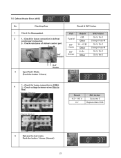
Check for loose connection in defrost control part connector. Check resistance of defrost control part. Check voltage between wires Blue to the 5 Def' Heater 3 Input Test 3 Mode. (Push the button 3 times) 1.- Part Result SVC Action 2 1.- Fuse M Def' Heater 34 ~ 42 Ω Other Go to the 3 Change Fuse-M Def' Sensor Def' Sensor 21 Ω↓ Other Go to the 3 Go to Red. Push the button 1 times. (Normal) 23 Result 112 ~ 116 V 0 V SVC Action Go to the 3 Change Fuse-M 2-. Fuse-M 0Ω Other Go to the 5 Replace Main PCB 5 Release the test mode. ...
Check for loose connection in defrost control part connector. Check resistance of defrost control part. Check voltage between wires Blue to the 5 Def' Heater 3 Input Test 3 Mode. (Push the button 3 times) 1.- Part Result SVC Action 2 1.- Fuse M Def' Heater 34 ~ 42 Ω Other Go to the 3 Change Fuse-M Def' Sensor Def' Sensor 21 Ω↓ Other Go to the 3 Go to Red. Push the button 1 times. (Normal) 23 Result 112 ~ 116 V 0 V SVC Action Go to the 3 Change Fuse-M 2-. Fuse-M 0Ω Other Go to the 5 Replace Main PCB 5 Release the test mode. ...
Service Manual
Page 24
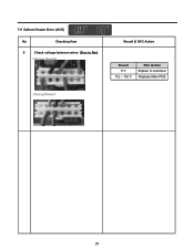
Result & SVC Action Result 0 V 112 ~ 116 V SVC Action Explain to Red. 7-5 Defrost Heater Error (dH E) No Checking flow 6 Check voltage between wires Blue to customer Replace Main PCB 24
Result & SVC Action Result 0 V 112 ~ 116 V SVC Action Explain to Red. 7-5 Defrost Heater Error (dH E) No Checking flow 6 Check voltage between wires Blue to customer Replace Main PCB 24
Service Manual
Page 25
It feel sticky, change the motor. (Cause of ice or rust inside of motor) 4 1.- Check for loose connection in CON7. 2-. Status No windy Windy SVC Action Go to 3 Go to 4 Rotate fan using your hand. Check fan motor voltage. Point (2)~(3) (1)~(3) Result Below 7V 0 or 5 V SVC Action Change the PCB Change the motor (3)(2)(1) (3)(2)(1) 25 7-6 Freezer Fan Error (FF E) No Checking flow 1 Reset the unit and Input Test 1 Mode. (Push the button 1 time) Result & SVC Action 2 Open the freezer door and Check the air flow. ※ While an error code is displayed, the fan ...
It feel sticky, change the motor. (Cause of ice or rust inside of motor) 4 1.- Check for loose connection in CON7. 2-. Status No windy Windy SVC Action Go to 3 Go to 4 Rotate fan using your hand. Check fan motor voltage. Point (2)~(3) (1)~(3) Result Below 7V 0 or 5 V SVC Action Change the PCB Change the motor (3)(2)(1) (3)(2)(1) 25 7-6 Freezer Fan Error (FF E) No Checking flow 1 Reset the unit and Input Test 1 Mode. (Push the button 1 time) Result & SVC Action 2 Open the freezer door and Check the air flow. ※ While an error code is displayed, the fan ...
Service Manual
Page 26
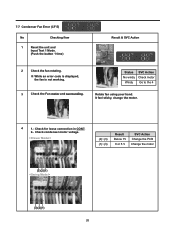
Check for loose connection in CON7. 2-. Check condenser motor voltage. (2)~(3) (1)~(3) Result Below 7V 0 or 5 V SVC Action Change the PCB Change the motor (3)(2)(1) (3)(2)(1) 26 7-7 Condenser Fan Error (CF E) No Checking flow 1 Reset the unit and Input Test 1 Mode. (Push the button 1 time) Result & SVC Action 2 Check the fan rotating. ※ While an error code is displayed, the fan is not working. 3 Check the Fan motor and surrounding. It feel sticky, change the motor. 4 1.- Status SVC Action No windy Check motor Windy Go to the 4 Rotate fan using your hand.
Check for loose connection in CON7. 2-. Check condenser motor voltage. (2)~(3) (1)~(3) Result Below 7V 0 or 5 V SVC Action Change the PCB Change the motor (3)(2)(1) (3)(2)(1) 26 7-7 Condenser Fan Error (CF E) No Checking flow 1 Reset the unit and Input Test 1 Mode. (Push the button 1 time) Result & SVC Action 2 Check the fan rotating. ※ While an error code is displayed, the fan is not working. 3 Check the Fan motor and surrounding. It feel sticky, change the motor. 4 1.- Status SVC Action No windy Check motor Windy Go to the 4 Rotate fan using your hand.
Service Manual
Page 27
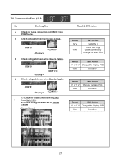
CON101 4 Check voltage between wires Blue to Yellow. Result & SVC Action Result 12 V Other SVC Action Go to the 3 Check the Hinge (loose connection) Change the Main PCB Result 0 V or 5 V Other SVC Action Change the Display PCB Go to the 4 Result 0 V or 5 V Other SVC Action Change the Main PCB Go to the 5 Result 0 V or 5 V Other SVC Action Change the Display PCB Go to Blue. Check for loose connection in CON5 5 from PCB Display. 2 Check voltage between wires Blue to Yellow. CON101 1.- CON101 3 Check voltage between wires Blue to Purple. 7-8 ...
CON101 4 Check voltage between wires Blue to Yellow. Result & SVC Action Result 12 V Other SVC Action Go to the 3 Check the Hinge (loose connection) Change the Main PCB Result 0 V or 5 V Other SVC Action Change the Display PCB Go to the 4 Result 0 V or 5 V Other SVC Action Change the Main PCB Go to the 5 Result 0 V or 5 V Other SVC Action Change the Display PCB Go to Blue. Check for loose connection in CON5 5 from PCB Display. 2 Check voltage between wires Blue to Yellow. CON101 1.- CON101 3 Check voltage between wires Blue to Purple. 7-8 ...
Service Manual
Page 28
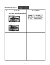
Result & SVC Action Result 0 V or 5 V Other SVC Action Change the Main PCB Explain to Purple. 7-8 Communication Error (CO E) No Checking flow 6 Check voltage between wires Blue to customer 28
Result & SVC Action Result 0 V or 5 V Other SVC Action Change the Main PCB Explain to Purple. 7-8 Communication Error (CO E) No Checking flow 6 Check voltage between wires Blue to customer 28
Service Manual
Page 29
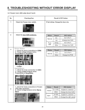
Status Normal Push S/W Result 0 not Infinity Other SVC Action Go to the 3 Change door S/W Go to the 3 Change door S/W Status Normal Result 12 V Other SVC Action Go to Gray/White. Check voltage between wires Purple/White to the 4 Change the PCB 1.- Check voltage between wires Red to Black. Check for loose connection in CON7. 2-. Check for loose connection in CON8. 2-. Status Closed Open Result 0~2 VDC Other 12 VDC Other SVC Action Explain to customer Change the Door S/W Explain to Gray/White. 1.- Result & SVC Action If feel sticky, Change the door s/w. 2 ...
Status Normal Push S/W Result 0 not Infinity Other SVC Action Go to the 3 Change door S/W Go to the 3 Change door S/W Status Normal Result 12 V Other SVC Action Go to Gray/White. Check voltage between wires Purple/White to the 4 Change the PCB 1.- Check voltage between wires Red to Black. Check for loose connection in CON7. 2-. Check for loose connection in CON8. 2-. Status Closed Open Result 0~2 VDC Other 12 VDC Other SVC Action Explain to customer Change the Door S/W Explain to Gray/White. 1.- Result & SVC Action If feel sticky, Change the door s/w. 2 ...
Service Manual
Page 30
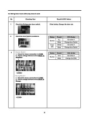
Status Normal Push S/W Result 0 Other Infinity Other SVC Action Go to the 3 Change door Switch Go to the 3 Change door Switch Status Normal Result 12 V Other SVC Action Go to Gray/Red . Result & SVC Action If feel sticky, Change the door s/w. 2 Check the door Switch resistance. 3 1.- Check voltage between wires Black to Orange. 30 Check for loose connection in CON8. 2-. Check for loose connection in CON5. 2-. 8-2 Refrigerator room LED Lamp doesn't work No Checking flow 1 Check the Refrigerator door switch. Check voltage between wires Black to the 4 Change the PCB...
Status Normal Push S/W Result 0 Other Infinity Other SVC Action Go to the 3 Change door Switch Go to the 3 Change door Switch Status Normal Result 12 V Other SVC Action Go to Gray/Red . Result & SVC Action If feel sticky, Change the door s/w. 2 Check the door Switch resistance. 3 1.- Check voltage between wires Black to Orange. 30 Check for loose connection in CON8. 2-. Check for loose connection in CON5. 2-. 8-2 Refrigerator room LED Lamp doesn't work No Checking flow 1 Check the Refrigerator door switch. Check voltage between wires Black to the 4 Change the PCB...
Service Manual
Page 32
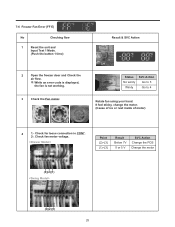
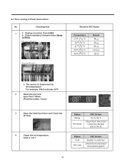
Status Windy No windy SVC Action Go to the 4 Check the F Fan motor Check the damper (Go to the 5) Status Cold Not cold SVC Action Explain to White. Result & SVC Action Temperature 23°F °C 32°F °C 41°F °C 50°F °C 59°F °C Result 38 30 24 19.5 16 The sensor is determined by the temperature. For example, 30kΩ indicates 32°F. 2 Reset the unit and Input Test 1 Mode. (Push the button 1 time) 3 Open the fresh food door and Check the air flow. 4 Check the air temperature. Check resistance between wires White...
Status Windy No windy SVC Action Go to the 4 Check the F Fan motor Check the damper (Go to the 5) Status Cold Not cold SVC Action Explain to White. Result & SVC Action Temperature 23°F °C 32°F °C 41°F °C 50°F °C 59°F °C Result 38 30 24 19.5 16 The sensor is determined by the temperature. For example, 30kΩ indicates 32°F. 2 Reset the unit and Input Test 1 Mode. (Push the button 1 time) 3 Open the fresh food door and Check the air flow. 4 Check the air temperature. Check resistance between wires White...
Service Manual
Page 33
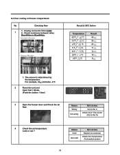
Check resistance between wires Blue/White to customer Check the Compressor And sealed system 33 Status Cold Not cold SVC Action Explain to Blue/White. 8-4 Poor cooling in Freezer compartment No Checking flow 1-. Status Windy No windy SVC Action Go to the 4 Check the F Fan motor (Go to the 5) 4 Check the air temperature. Result & SVC Action Temperature -22°F °C -13°F °C -4°F °C 5°F °C 14°F °C 23°F °C 32°F °C Result 40 30 23 17 13 10 8 The sensor is determined by the temperature. Cold or ...
Check resistance between wires Blue/White to customer Check the Compressor And sealed system 33 Status Cold Not cold SVC Action Explain to Blue/White. 8-4 Poor cooling in Freezer compartment No Checking flow 1-. Status Windy No windy SVC Action Go to the 4 Check the F Fan motor (Go to the 5) 4 Check the air temperature. Result & SVC Action Temperature -22°F °C -13°F °C -4°F °C 5°F °C 14°F °C 23°F °C 32°F °C Result 40 30 23 17 13 10 8 The sensor is determined by the temperature. Cold or ...


