Service Manual
Page 2
...and fan motor (Evaporator 7 3-5 Defrost Control Assembly 7 3-6 Lamp 8 3-7 MultiDuct 8 3-8 Main PWB 8 3-9 How to electric elements or the machine parts. 7. COMPRESSOR ELECTRICAL 12 4-1 Compressor Freezer Drawer model 12 4-2 Compressor Freezer Swing model 13 4-3 PTC-Starter 13 4-4 OLP (Overload Protector 14 5. COMPRESSOR ...2. When servicing the evaporator, wear gloves to prevent injuries from spiling on or in the freezer with wet hands. PARTS IDENTIFICATION 4 3. This may cause frost bite. 6. Always check line voltage and amperage. 4. ICE MAKER AND DISPENSER...
...and fan motor (Evaporator 7 3-5 Defrost Control Assembly 7 3-6 Lamp 8 3-7 MultiDuct 8 3-8 Main PWB 8 3-9 How to electric elements or the machine parts. 7. COMPRESSOR ELECTRICAL 12 4-1 Compressor Freezer Drawer model 12 4-2 Compressor Freezer Swing model 13 4-3 PTC-Starter 13 4-4 OLP (Overload Protector 14 5. COMPRESSOR ...2. When servicing the evaporator, wear gloves to prevent injuries from spiling on or in the freezer with wet hands. PARTS IDENTIFICATION 4 3. This may cause frost bite. 6. Always check line voltage and amperage. 4. ICE MAKER AND DISPENSER...
Service Manual
Page 4
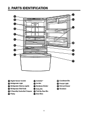
2. PARTS IDENTIFICATION J A B K C L D E F M G H N I O P A Digital Sensor Control B Refrigerator Light C Refrigerator Shelves (split) D Refrigerator Shelf (full) E E Humidity Controlled Crispers F Pantry G Icemaker* H Ice Bin I Durabase Divider J Dairy Bin K Fold-Up Door Bin L Door Bins M Condiment Bin N Freezer Light O Pull out Drawer P Durabase 4
2. PARTS IDENTIFICATION J A B K C L D E F M G H N I O P A Digital Sensor Control B Refrigerator Light C Refrigerator Shelves (split) D Refrigerator Shelf (full) E E Humidity Controlled Crispers F Pantry G Icemaker* H Ice Bin I Durabase Divider J Dairy Bin K Fold-Up Door Bin L Door Bins M Condiment Bin N Freezer Light O Pull out Drawer P Durabase 4
Service Manual
Page 6
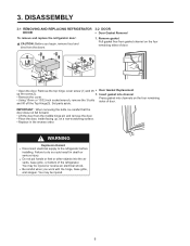
... air vents, base grille, or bottom of door. (1) (1) (2) • Open the door. Insert gasket into channels on the four remaining sides of the refrigerator. Set parts aside. You may be injured or receive an electrical shock. Remove gasket Pull gasket free from gasket channel on the four remaining sides of door...
... air vents, base grille, or bottom of door. (1) (1) (2) • Open the door. Insert gasket into channels on the four remaining sides of the refrigerator. Set parts aside. You may be injured or receive an electrical shock. Remove gasket Pull gasket free from gasket channel on the four remaining sides of door...
Service Manual
Page 12
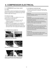
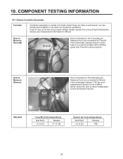
... liquid. Lock Piston Trip If stroke is under 5mm even if the current is above the target value, decrease the target volt by part number and model number. For every 416.7us, check whether FO signal is LOW. Stroke Trip During the operation, if stroke is ... PTC Compressor may appear physically identical but could have protection logic for Usage (1) Be careful not to high-temperature and high-pressure gas. Replace parts by 3V. - COMPRESSOR ELECTRICAL 4-1 COMPRESSOR (Freezer Drawer model) 4-1-1 Role The compressor intakes low temperature and low pressure gas from the overcurrent ...
... liquid. Lock Piston Trip If stroke is under 5mm even if the current is above the target value, decrease the target volt by part number and model number. For every 416.7us, check whether FO signal is LOW. Stroke Trip During the operation, if stroke is ... PTC Compressor may appear physically identical but could have protection logic for Usage (1) Be careful not to high-temperature and high-pressure gas. Replace parts by 3V. - COMPRESSOR ELECTRICAL 4-1 COMPRESSOR (Freezer Drawer model) 4-1-1 Role The compressor intakes low temperature and low pressure gas from the overcurrent ...
Service Manual
Page 13
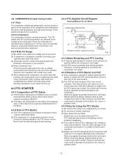
...the PTC allows current flow to both the start condition. (5) Always use extreme caution when repairing it must be altered. Replace parts by part number and model number. This can cause damage to the compressor and result in damage to restart until the PTC device has cooled...correct OLP must be allowed to cool before the compressor can restart. (2) The PTC device generates heat during operation. Using an incorrect part could have different electrical ratings. Since the compressor is manufactured to tolerances of PTC-Starter (1) PTC (Positive Temperature Coefficient) is a no...
...the PTC allows current flow to both the start condition. (5) Always use extreme caution when repairing it must be altered. Replace parts by part number and model number. This can cause damage to the compressor and result in damage to restart until the PTC device has cooled...correct OLP must be allowed to cool before the compressor can restart. (2) The PTC device generates heat during operation. Using an incorrect part could have different electrical ratings. Since the compressor is manufactured to tolerances of PTC-Starter (1) PTC (Positive Temperature Coefficient) is a no...
Service Manual
Page 14
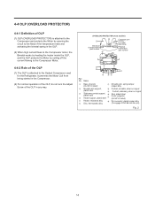
... the temperature rises and activating the bimetal spring in any way. (OVERLOAD PROTECTOR cross section) Electrical 330 FBYY characteristics part number 12345678 -S1 BOX98 Customer part number Lot code/ date code Physical termination part number Part No. Name Base, phenolic (UL 94 V-0 rated) Movable arm support, plated steel. Stationary contact support, plated steel Heater...
... the temperature rises and activating the bimetal spring in any way. (OVERLOAD PROTECTOR cross section) Electrical 330 FBYY characteristics part number 12345678 -S1 BOX98 Customer part number Lot code/ date code Physical termination part number Part No. Name Base, phenolic (UL 94 V-0 rated) Movable arm support, plated steel. Stationary contact support, plated steel Heater...
Service Manual
Page 23
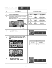
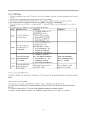
... for loose connection in CON3. 4 2-. Result 112 ~ 116 V 0 V SVC Action Go to Red. Check resistance of defrost control part. Push the button 1 times. (Normal) 23 Check for loose connection in defrost control part connector. Check voltage between wires Blue to the 5 Replace Main PCB 5 Release the test mode. Fuse-M 0Ω Other Go...
... for loose connection in CON3. 4 2-. Result 112 ~ 116 V 0 V SVC Action Go to Red. Check resistance of defrost control part. Push the button 1 times. (Normal) 23 Check for loose connection in defrost control part connector. Check voltage between wires Blue to the 5 Replace Main PCB 5 Release the test mode. Fuse-M 0Ω Other Go...
Service Manual
Page 39
... (Fuse-M) (1) to (2) Set a ohmmeter to Fuse-M. Standard Fuse-M (at all temperature) Test Point Ressult (1) to The 2housing pin. Fuse-m can decide part is disconnection How to Measure (Sensor) (1) to (2) Set a ohmmeter to (2) 0 ~ 0.1Ω Sensor (at other temperature Check the sensor manual. Measure ...Sensor. Controller assembly is not a defect. If the ohmmeter indicate 11㏀ (at room temperature) Sensor is consist of 2 kinds of part those are fuse-m and sensor. 10. If the ohmmeter indicate below 0.1ohm fuse-m is a good condition, But infinitely great ohm Fuse...
... (Fuse-M) (1) to (2) Set a ohmmeter to Fuse-M. Standard Fuse-M (at all temperature) Test Point Ressult (1) to The 2housing pin. Fuse-m can decide part is disconnection How to Measure (Sensor) (1) to (2) Set a ohmmeter to (2) 0 ~ 0.1Ω Sensor (at other temperature Check the sensor manual. Measure ...Sensor. Controller assembly is not a defect. If the ohmmeter indicate 11㏀ (at room temperature) Sensor is consist of 2 kinds of part those are fuse-m and sensor. 10. If the ohmmeter indicate below 0.1ohm fuse-m is a good condition, But infinitely great ohm Fuse...
Service Manual
Page 40
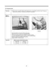
Measure the 2 pin connected to only one line. So we can decide part is a part for defrost. All heating wire is disconnection Sheath heater (at all temperature) Test Point Ressult (1) to The 2 housing pin. If the ohmmeter indicate (V°øV)/...
Measure the 2 pin connected to only one line. So we can decide part is a part for defrost. All heating wire is disconnection Sheath heater (at all temperature) Test Point Ressult (1) to The 2 housing pin. If the ohmmeter indicate (V°øV)/...
Service Manual
Page 51
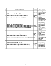
...-on - on -on - off repeating Cause Service guideline 1. If the same symptom arises after the first action 3. on - off PCB parts defect (IPM) repeating check if it is running normal 2. After the first action, You check on - on normal operation of compressor is ... LED six - on - on - on - off - After resetting power, 4 LED seven- off - on - off - on - Please check, Whether PCB Parts defect or Compress or Connector miss connecting (Piston over 3 current error on - on - on - on - time repetiton (IPM Fault Trip) on - on -on -...
...-on - on -on - off repeating Cause Service guideline 1. If the same symptom arises after the first action 3. on - off PCB parts defect (IPM) repeating check if it is running normal 2. After the first action, You check on - on normal operation of compressor is ... LED six - on - on - on - off - After resetting power, 4 LED seven- off - on - off - on - Please check, Whether PCB Parts defect or Compress or Connector miss connecting (Piston over 3 current error on - on - on - on - time repetiton (IPM Fault Trip) on - on -on -...
Service Manual
Page 52
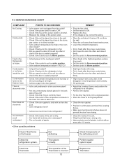
...'t open the door too often and close it firmly. • Set the control to Recommended position. • Place foods in the high-temperature section. (front part) • Set the control to Recommended position. • Set the control to ON. • Replace the fuse. • If the voltage is low, correct the...
...'t open the door too often and close it firmly. • Set the control to Recommended position. • Place foods in the high-temperature section. (front part) • Set the control to Recommended position. • Set the control to ON. • Replace the fuse. • If the voltage is low, correct the...
Service Manual
Page 53
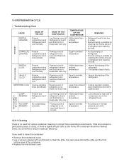
... significant pet traffic in the home, the condenser should be cleaned every 2 to 3 months to low refrigerant level. • No pressure in the high pressure part of refrigerant is not heard and frost isn't formed. REMARKS • Refrigerant level is heard and frost forms in normal Home operating environments. Low flowing...
... significant pet traffic in the home, the condenser should be cleaned every 2 to 3 months to low refrigerant level. • No pressure in the high pressure part of refrigerant is not heard and frost isn't formed. REMARKS • Refrigerant level is heard and frost forms in normal Home operating environments. Low flowing...
Service Manual
Page 61
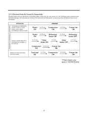
... 5 sec. are turned on and are started at the same time at initial power on in 0.5 sec. 13-1-9 Electrical Parts Are Turned On Sequentially Electrical parts such as compressor, defrosting heater, freezer fan, etc. Initial power in 0.5 sec. ON Freezer fan ON Reset to prevent ...noise and parts damage. Compressor ON in Temperature of defrosting OPERATING Temperature of defrosting sensor is 45°C or more ...
... 5 sec. are turned on and are started at the same time at initial power on in 0.5 sec. 13-1-9 Electrical Parts Are Turned On Sequentially Electrical parts such as compressor, defrosting heater, freezer fan, etc. Initial power in 0.5 sec. ON Freezer fan ON Reset to prevent ...noise and parts damage. Compressor ON in Temperature of defrosting OPERATING Temperature of defrosting sensor is 45°C or more ...
Service Manual
Page 63
... Test S/W(in the test mode, the test mode is cleared and the error code is displayed. 6. If an error, such as finding out the defective part in case of the product as well as a sensor failure, is detected while in the FREEZER/ Refrigerator fan OFF. The fan speed will start after...
... Test S/W(in the test mode, the test mode is cleared and the error code is displayed. 6. If an error, such as finding out the defective part in case of the product as well as a sensor failure, is detected while in the FREEZER/ Refrigerator fan OFF. The fan speed will start after...
Service Manual
Page 64
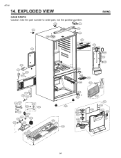
#EV# 14. EXPLODED VIEW SWING CASE PARTS Caution: Use the part number to order part, not the position number. 103B 281A 103A 282E 402A 281B 503F 501F 903D 120A 282F 145A 501A 411A 410G S38 282B 409C 128E 158E 301A 282D 105A 318A 317A 307A 314A 309A 310A 308A 312A 405F 420A 319F 329C 323B 405G 319D 128F 106A 305B 305C 315A 282C 283D 329A 405C 405C 405F 330B 401A 418A 316C 332C 316B 316A 610C 903E 305B 305C 64
#EV# 14. EXPLODED VIEW SWING CASE PARTS Caution: Use the part number to order part, not the position number. 103B 281A 103A 282E 402A 281B 503F 501F 903D 120A 282F 145A 501A 411A 410G S38 282B 409C 128E 158E 301A 282D 105A 318A 317A 307A 314A 309A 310A 308A 312A 405F 420A 319F 329C 323B 405G 319D 128F 106A 305B 305C 315A 282C 283D 329A 405C 405C 405F 330B 401A 418A 316C 332C 316B 316A 610C 903E 305B 305C 64
Service Manual
Page 65
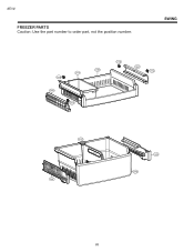
#EV# FREEZER PARTS Caution: Use the part number to order part, not the position number. SWING 133B 131A 145F 133A 136B 133B 145C 133A 237C 128F 128E 136D 65
#EV# FREEZER PARTS Caution: Use the part number to order part, not the position number. SWING 133B 131A 145F 133A 136B 133B 145C 133A 237C 128F 128E 136D 65
Service Manual
Page 66
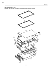
#EV# REFRIGERATOR PARTS Caution: Use the part number to order part, not the position number. 143A SWING 143A 145J S13 S38 145H 128B 167B 151C 151B S13 S38 145G 154A 151A 154B 133C 155B 160B 128A 170A 66
#EV# REFRIGERATOR PARTS Caution: Use the part number to order part, not the position number. 143A SWING 143A 145J S13 S38 145H 128B 167B 151C 151B S13 S38 145G 154A 151A 154B 133C 155B 160B 128A 170A 66
Service Manual
Page 67
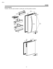
#EV# DOOR PARTS Caution: Use the part number to order part, not the position number. 241F 230A 233A 231A 212G 241E 237A 241C 237A 244A 244E SWING 241C 241D 243B 243A 286A 281E 203A 201A 200A 286A 243B 243A 286A 67
#EV# DOOR PARTS Caution: Use the part number to order part, not the position number. 241F 230A 233A 231A 212G 241E 237A 241C 237A 244A 244E SWING 241C 241D 243B 243A 286A 281E 203A 201A 200A 286A 243B 243A 286A 67
Service Manual
Page 68
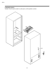
#EV# ICEMAKER PARTS Caution: Use the part number to order part, not the position number. 600A 627A 619C 68
#EV# ICEMAKER PARTS Caution: Use the part number to order part, not the position number. 600A 627A 619C 68


