

Owner's Manual
Page 2
..., never touch the power cord and signal cable because it is not operating properly. There are no user serviceable components inside , even when the power is faulty in potential electrical shock or fire hazards. To Avoid Personal Injury : Do not place the display on or apply impact to allow the proper operation of all safeguards incorporated in the specifications of...
..., never touch the power cord and signal cable because it is not operating properly. There are no user serviceable components inside , even when the power is faulty in potential electrical shock or fire hazards. To Avoid Personal Injury : Do not place the display on or apply impact to allow the proper operation of all safeguards incorporated in the specifications of...

Owner's Manual
Page 3
... over the power cord, and do not place the display where the power cord is subject to damage. If used in this is easy to obtain the best image quality for a long time as this will have no impact or effect on a bed, sofa, rug, etc. On Disposal The fluorescent lamp used under any mode except the recommended resolution, some afterimages...
... over the power cord, and do not place the display where the power cord is subject to damage. If used in this is easy to obtain the best image quality for a long time as this will have no impact or effect on a bed, sofa, rug, etc. On Disposal The fluorescent lamp used under any mode except the recommended resolution, some afterimages...

Owner's Manual
Page 4
Connecting the stand 1. Stand Base Stand Body 4. Your monitor may fall and get damaged or injure your foot. Stand Body Hinge Body 3. Insert the Cable Deco Cover in the Stand Body in the picture. Stand Base Stand Body Cable Deco Cover Cable Deco Cover 5. Once assembled take the monitor up the monitor, ensure that the power to the monitor, the computer system, and other attached devices is turned off. A3 Do not carry the product...
Connecting the stand 1. Stand Base Stand Body 4. Your monitor may fall and get damaged or injure your foot. Stand Body Hinge Body 3. Insert the Cable Deco Cover in the Stand Body in the picture. Stand Base Stand Body Cable Deco Cover Cable Deco Cover 5. Once assembled take the monitor up the monitor, ensure that the power to the monitor, the computer system, and other attached devices is turned off. A3 Do not carry the product...

Owner's Manual
Page 5
Place the monitor face down on a flat surface. 2. A4 Put a cushion or soft cloth on the cushion or soft cloth. 3. Connecting the Display Disassembling the stand 1. Nip Latch inside, Take off the stand base from the hinge body. Please pull the stand body lightly to separate it from stand body. 5. Slide the Cable Deco Cover out from the stand body. 4.
Place the monitor face down on a flat surface. 2. A4 Put a cushion or soft cloth on the cushion or soft cloth. 3. Connecting the Display Disassembling the stand 1. Nip Latch inside, Take off the stand base from the hinge body. Please pull the stand body lightly to separate it from stand body. 5. Slide the Cable Deco Cover out from the stand body. 4.

Owner's Manual
Page 6
Adjust the position of the monitor should not exceed 5 degrees. A5 Connecting the Display Before setting up the monitor, ensure that in order to the monitor, the computer system, and other attached devices is recommended that the power to maintain an ergonomic and comfortable viewing position, the forward tilt angle of the panel in various ways for maximum comfort. Positioning your display 1. Tilt Range: -5˚~20˚ Ergonomic It is turned off.
Adjust the position of the monitor should not exceed 5 degrees. A5 Connecting the Display Before setting up the monitor, ensure that in order to the monitor, the computer system, and other attached devices is recommended that the power to maintain an ergonomic and comfortable viewing position, the forward tilt angle of the panel in various ways for maximum comfort. Positioning your display 1. Tilt Range: -5˚~20˚ Ergonomic It is turned off.

Owner's Manual
Page 7
...) D-sub VGA connector on the supplied cable to turn the power on the front switch panel to improve resolution. This function provides the user with optimal display settings.When the user connects the monitor for individual input signals. 'AUTO' Function? Connect the cable as below sketch map form 1 to optimal settings for the first time, this function automatically adjusts the display to 2 . Insert the Cable Deco Cover in the Stand Body in the picture. When you encounter problems such as...
...) D-sub VGA connector on the supplied cable to turn the power on the front switch panel to improve resolution. This function provides the user with optimal display settings.When the user connects the monitor for individual input signals. 'AUTO' Function? Connect the cable as below sketch map form 1 to optimal settings for the first time, this function automatically adjusts the display to 2 . Insert the Cable Deco Cover in the Stand Body in the picture. When you encounter problems such as...

Owner's Manual
Page 8
... cannot be inadvertently changed. OSD LOCKED/UNLOCKED This function allows you to enter or exit the On Screen Display. The message "OSD LOCKED" should appear. You can unlock the OSD controls at any time by pushing the MENU button for several seconds. This will automatically adjust your display settings, always press the AUTO button before entering the On Screen Display(OSD). Control Panel Functions Front Panel Controls AUTO Button MENU Button AUTO IMAGE ADJUSTMENT When adjusting your display image to the ideal settings for the current screen resolution size (display mode).
... cannot be inadvertently changed. OSD LOCKED/UNLOCKED This function allows you to enter or exit the On Screen Display. The message "OSD LOCKED" should appear. You can unlock the OSD controls at any time by pushing the MENU button for several seconds. This will automatically adjust your display settings, always press the AUTO button before entering the On Screen Display(OSD). Control Panel Functions Front Panel Controls AUTO Button MENU Button AUTO IMAGE ADJUSTMENT When adjusting your display image to the ideal settings for the current screen resolution size (display mode).
Owner's Manual
Page 9
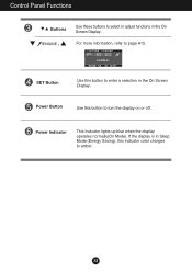
For more information, refer to enter a selection in the On Screen Display. SET Button Use this button to page A15. Power Button Use this button to amber. Power Indicator This Indicator lights up blue when the display operates normally(On Mode). A8 If the display is in the On Screen Display. Control Panel Functions Buttons Use these buttons to select or adjust functions in Sleep Mode (Energy Saving), this indicator color changes to turn the display on or off.
For more information, refer to enter a selection in the On Screen Display. SET Button Use this button to page A15. Power Button Use this button to amber. Power Indicator This Indicator lights up blue when the display operates normally(On Mode). A8 If the display is in the On Screen Display. Control Panel Functions Buttons Use these buttons to select or adjust functions in Sleep Mode (Energy Saving), this indicator color changes to turn the display on or off.

Owner's Manual
Page 10
... a control, use of the OSD appears. Push the MENU Button twice to stabilize for at least 30 minutes before making image adjustments. On Screen Display (OSD) Control Adjustment Screen Adjustment Making adjustments to the image size, position and operating parameters of the display is an outline of the available adjustments and selections you can make adjustments in the On Screen Display, follow these steps: MENU SET MENU Press the MENU Button, then the main menu of the controls. The following section is quick and...
... a control, use of the OSD appears. Push the MENU Button twice to stabilize for at least 30 minutes before making image adjustments. On Screen Display (OSD) Control Adjustment Screen Adjustment Making adjustments to the image size, position and operating parameters of the display is an outline of the available adjustments and selections you can make adjustments in the On Screen Display, follow these steps: MENU SET MENU Press the MENU Button, then the main menu of the controls. The following section is quick and...

Owner's Manual
Page 11
... RED sRGB 6500K 9300K GREEN BLUE HORIZONTAL VERTICAL CLOCK TRACKING PHASE SHARPNESS SETUP LANGUAGE OSD HORIZONTAL POSITION VERTICAL WHITE BALANCE POWER INDICATOR 4:3 IN WIDE FACTORY RESET FLATRON F-ENGINE MOVIE / TEXT USER NORMAL A Reference To adjust the brightness, contrast and gamma of the screen To customize the color of the screen To adjust the position of the screen To improve the clarity and stability of the screen To customize the screen status for a user's operating environment To select or customize desired image settings : Adjustable A : Analog Input...
... RED sRGB 6500K 9300K GREEN BLUE HORIZONTAL VERTICAL CLOCK TRACKING PHASE SHARPNESS SETUP LANGUAGE OSD HORIZONTAL POSITION VERTICAL WHITE BALANCE POWER INDICATOR 4:3 IN WIDE FACTORY RESET FLATRON F-ENGINE MOVIE / TEXT USER NORMAL A Reference To adjust the brightness, contrast and gamma of the screen To customize the color of the screen To adjust the position of the screen To improve the clarity and stability of the screen To customize the screen status for a user's operating environment To select or customize desired image settings : Adjustable A : Analog Input...

Owner's Manual
Page 12
Press the MENU Button, then the main menu of selecting and adjusting an item using the OSD system. A11 Menu Name PICTURE Icons Sub-menus Button Tip MENU : Exit : Adjust (Decrease/Increase) SET : Enter : Select another sub-menu NOTE OSD (On Screen Display) menu languages on the Menu. On Screen Display(OSD) Selection and Adjustment You were introduced to the procedure of the OSD appears. Listed below are the icons, icon names, and icon descriptions of the all items shown on the monitor may differ from the manual.
Press the MENU Button, then the main menu of selecting and adjusting an item using the OSD system. A11 Menu Name PICTURE Icons Sub-menus Button Tip MENU : Exit : Adjust (Decrease/Increase) SET : Enter : Select another sub-menu NOTE OSD (On Screen Display) menu languages on the Menu. On Screen Display(OSD) Selection and Adjustment You were introduced to the procedure of the OSD appears. Listed below are the icons, icon names, and icon descriptions of the all items shown on the monitor may differ from the manual.

Owner's Manual
Page 13
... own green color levels. On Screen Display(OSD) Selection and Adjustment Main menu Sub menu Description PICTURE PICTURE BRIGHTNESS CONTRAST GAMMA MENU : Exit : Decrease : Increase SET : Select another sub-menu • sRGB: Set the screen color to fit the SRGB standard color specification. • 6500K: Slightly reddish white. • 9300K: Slightly bluish white. Set your own blue color levels. To adjust the contrast of the screen. Set your own gamma value. : -50/0/50 On the monitor, high gamma values display whitish images...
... own green color levels. On Screen Display(OSD) Selection and Adjustment Main menu Sub menu Description PICTURE PICTURE BRIGHTNESS CONTRAST GAMMA MENU : Exit : Decrease : Increase SET : Select another sub-menu • sRGB: Set the screen color to fit the SRGB standard color specification. • 6500K: Slightly reddish white. • 9300K: Slightly bluish white. Set your own blue color levels. To adjust the contrast of the screen. Set your own gamma value. : -50/0/50 On the monitor, high gamma values display whitish images...

Owner's Manual
Page 14
... display. PHASE To adjust the focus of characters. This item allows you to remove any vertical bars or stripes visible on the screen background. MENU : Exit : Decrease : Increase SHARPNESS To adjust the clearness of the screen. On Screen Display(OSD) Selection and Adjustment Main menu Sub menu Description POSITION POSITION HORIZONTAL VERTICAL To move image up and down. To move image left and right. MENU : Exit : Decrease : Increase SET : Select another sub-menu...
... display. PHASE To adjust the focus of characters. This item allows you to remove any vertical bars or stripes visible on the screen background. MENU : Exit : Decrease : Increase SHARPNESS To adjust the clearness of the screen. On Screen Display(OSD) Selection and Adjustment Main menu Sub menu Description POSITION POSITION HORIZONTAL VERTICAL To move image up and down. To move image left and right. MENU : Exit : Decrease : Increase SET : Select another sub-menu...

Owner's Manual
Page 15
... optimized screen ratio. (The 1280x1024 input signal is changed to 5:4 ratio and 1024x768 to 4:3.) Resolution Screen ratio FACTORY RESET 1280x1024 5 : 4 1152x864 4 : 3 1024x768 4 : 3 800x600 4 : 3 640x480 4 : 3 720x480 3 : 2 ❈ The input signal which the control names are present in the screen. If this function when white and black colors are displayed. To adjust position of the OSD window on . 4:3 IN WIDE To select the image size of the video card is the following 720x400,1280x768,1360x768,1440x900. @@@@@@@@f f f f Restore all factory default settings...
... optimized screen ratio. (The 1280x1024 input signal is changed to 5:4 ratio and 1024x768 to 4:3.) Resolution Screen ratio FACTORY RESET 1280x1024 5 : 4 1152x864 4 : 3 1024x768 4 : 3 800x600 4 : 3 640x480 4 : 3 720x480 3 : 2 ❈ The input signal which the control names are present in the screen. If this function when white and black colors are displayed. To adjust position of the OSD window on . 4:3 IN WIDE To select the image size of the video card is the following 720x400,1280x768,1360x768,1440x900. @@@@@@@@f f f f Restore all factory default settings...

Owner's Manual
Page 16
....Touch the SET button to the environment (ambient illumination, image types etc). Menu Name Icons Sub-menu Name button at the bottom FLATRON F-ENGINE When you touch the of the monitor. To adjust the USER sub-menu function, Press the SET Button USER BRIGHTNESS ACE 1 RCM 2 SAVE ... (Brightness): Adjusts screen brightness. ...ACE(Adaptive Clarity Enhancer): Selects the clarity mode. ...RCM(Real Color Management): Selects the color mode. 0 Not applied 1 Green enhance 2 Flesh tone 3 Color Enhance Select the SAVE sub-menu using the SET button...
....Touch the SET button to the environment (ambient illumination, image types etc). Menu Name Icons Sub-menu Name button at the bottom FLATRON F-ENGINE When you touch the of the monitor. To adjust the USER sub-menu function, Press the SET Button USER BRIGHTNESS ACE 1 RCM 2 SAVE ... (Brightness): Adjusts screen brightness. ...ACE(Adaptive Clarity Enhancer): Selects the clarity mode. ...RCM(Real Color Management): Selects the color mode. 0 Not applied 1 Green enhance 2 Flesh tone 3 Color Enhance Select the SAVE sub-menu using the SET button...

Owner's Manual
Page 17
... see if the power cord is not connected. A16 Check the signal cable and try moving the mouse or pressing any time by pushing the MENU button for service. frequency range of horizontal or vertical the screen? See the 'Specifications' section of the • Check and see a "OSD LOCKED" message on and the • Adjust the brightness and the contrast. No image appears ● Is the power cord of this manual and configure your display is connected display connected?
... see if the power cord is not connected. A16 Check the signal cable and try moving the mouse or pressing any time by pushing the MENU button for service. frequency range of horizontal or vertical the screen? See the 'Specifications' section of the • Check and see a "OSD LOCKED" message on and the • Adjust the brightness and the contrast. No image appears ● Is the power cord of this manual and configure your display is connected display connected?

Owner's Manual
Page 18
... AUTO button to automatically adjust your display image to the ideal setting. If the input resolution is not 16:10 (for Recommending Optimal Resolution : The aspect ratio is incorrect. • Press the AUTO button to automatically adjust your display image to the ideal setting. Important Check Control Panel --> Display --> Settings and see if the frequency or the resolution were changed. In this case, please ask to the recommend resolution. Set the color setting higher than 24 bits (true color...
... AUTO button to automatically adjust your display image to the ideal setting. If the input resolution is not 16:10 (for Recommending Optimal Resolution : The aspect ratio is incorrect. • Press the AUTO button to automatically adjust your display image to the ideal setting. Important Check Control Panel --> Display --> Settings and see if the frequency or the resolution were changed. In this case, please ask to the recommend resolution. Set the color setting higher than 24 bits (true color...

Owner's Manual
Page 19
...; Do you installed the display driver? • Be sure to check if the video card supports Plug&Play function. Settings. ● The screen blinks. • Check if the screen is set to interlace mode and if yes, change it to fasten if necessary. • Make sure the video card is properly connected and use a screwdriver to the recommend resolution. Troubleshooting Display image is incorrect ● The screen color is mono or abnormal. • Check if the signal cable is properly...
...; Do you installed the display driver? • Be sure to check if the video card supports Plug&Play function. Settings. ● The screen blinks. • Check if the screen is set to interlace mode and if yes, change it to fasten if necessary. • Make sure the video card is properly connected and use a screwdriver to the recommend resolution. Troubleshooting Display image is incorrect ● The screen color is mono or abnormal. • Check if the signal cable is properly...

Owner's Manual
Page 20
...˚C to 60 ˚C Humidity 5 % to 90 % non-Condensing Attached( ), Detached ( O ) Wall-outlet type or PC-outlet type NOTE Information in this document is subject to change without notice. A19 Vertical Freq. Specifications Display Sync Input Video Input Resolution Plug&Play Power Consumption Dimensions &Weight Tilt Range Power Input Environmental Conditions Stand Base Power cord 17 inches (43.3 cm) Flat Panel Active matrix-TFT LCD Anti-Glare coating 17 inches viewable 0.255*0.255 mm pixel pitch Horizontal Freq.
...˚C to 60 ˚C Humidity 5 % to 90 % non-Condensing Attached( ), Detached ( O ) Wall-outlet type or PC-outlet type NOTE Information in this document is subject to change without notice. A19 Vertical Freq. Specifications Display Sync Input Video Input Resolution Plug&Play Power Consumption Dimensions &Weight Tilt Range Power Input Environmental Conditions Stand Base Power cord 17 inches (43.3 cm) Flat Panel Active matrix-TFT LCD Anti-Glare coating 17 inches viewable 0.255*0.255 mm pixel pitch Horizontal Freq.

Owner's Manual
Page 21
Specifications Preset Modes (Resolution) Display Modes (Resolution) 1 640 x 350 2 720 x 400 3 640 x 480 4 640 x 480 5 800 x 600 6 800 x 600 7 832 x 624 8 1024 x 768 9 1024 x 768 10 1152 x 870 11 1152 x 900 12 1280 x 1024 13 1280 x 1024 14 1440 x 900 *15 1440 x 900 16 1440 x 900 Horizontal Freq. (kHz) 31.469 31.468 31.469 37.500 37.879 46.875 49.725 48.363 60.123 68.681 61.805 63.981 79.976 55.5 55.935 70.635 Vertical Freq. (Hz) 70 70 60 75 60 75 75 60 75 75 65 60 75 60 60 75 * Recommend Mode Indicator MODE On Mode Sleep Mode Off Mode LED Color blue amber Off A20
Specifications Preset Modes (Resolution) Display Modes (Resolution) 1 640 x 350 2 720 x 400 3 640 x 480 4 640 x 480 5 800 x 600 6 800 x 600 7 832 x 624 8 1024 x 768 9 1024 x 768 10 1152 x 870 11 1152 x 900 12 1280 x 1024 13 1280 x 1024 14 1440 x 900 *15 1440 x 900 16 1440 x 900 Horizontal Freq. (kHz) 31.469 31.468 31.469 37.500 37.879 46.875 49.725 48.363 60.123 68.681 61.805 63.981 79.976 55.5 55.935 70.635 Vertical Freq. (Hz) 70 70 60 75 60 75 75 60 75 75 65 60 75 60 60 75 * Recommend Mode Indicator MODE On Mode Sleep Mode Off Mode LED Color blue amber Off A20


