

Service Manual
Page 2
... (SKY77318) ....22 3.3 26 MHz Clock (DCXO 24 3.4 RTC(32.768KHz Crystal 25 3.5 LCD Interface(3-wire SPI interface) .......26 3.6 SIM Card Interface 28 3.7 KEYPAD Interface 29 3.8 Battery Charging Block Interface ...........30 3.9 RF Interface 31 3.10 Audio Interface 33 3.11 Key LED Interface 37 3.12 Vibrator Interface 38 3.13 Memory Interface 39 3.14...
... (SKY77318) ....22 3.3 26 MHz Clock (DCXO 24 3.4 RTC(32.768KHz Crystal 25 3.5 LCD Interface(3-wire SPI interface) .......26 3.6 SIM Card Interface 28 3.7 KEYPAD Interface 29 3.8 Battery Charging Block Interface ...........30 3.9 RF Interface 31 3.10 Audio Interface 33 3.11 Key LED Interface 37 3.12 Vibrator Interface 38 3.13 Memory Interface 39 3.14...
Service Manual
Page 6
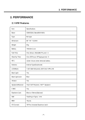
... Li-ion Talk Time Over 2hours @EGSM,TX Level : 5 Stand-by Time Over 200 hours @Paging period : 5 RTC Under 4 hours when removed battery. 2. Antenna Internal Type(Dual-band) LCD(Main) 1.52"(128x128 pixels), 65K Color STN LCD Back Light Yes Back Light color Blue Vibrator Yes Speaker&Receiver ...
... Li-ion Talk Time Over 2hours @EGSM,TX Level : 5 Stand-by Time Over 200 hours @Paging period : 5 RTC Under 4 hours when removed battery. 2. Antenna Internal Type(Dual-band) LCD(Main) 1.52"(128x128 pixels), 65K Color STN LCD Back Light Yes Back Light color Blue Vibrator Yes Speaker&Receiver ...
Service Manual
Page 8
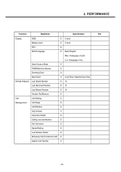
... O Full Call divert O Speed Dialing O Last Number Redial O Multi-party Call (Conference Call) O Explicit Call Transfer X -9- PERFORMANCE Function Detail Item Specification Etc. Display RSSI O 6 level Battery Level O 5 level RTC O Multi?Language O Basic:English Max. 4 language of Latin 2 or 3 language of etc.
... O Full Call divert O Speed Dialing O Last Number Redial O Multi-party Call (Conference Call) O Explicit Call Transfer X -9- PERFORMANCE Function Detail Item Specification Etc. Display RSSI O 6 level Battery Level O 5 level RTC O Multi?Language O Basic:English Max. 4 language of Latin 2 or 3 language of etc.

Service Manual
Page 12
... strap X LCD Cleaner X Holster X Data cable O RS232 cable Option CD X Holster charger X Standard battery Back-up and Holster function additional standard battery X Extended Battery X Desktop Charger X Cigar Lighter Adapter X Portable Handsfree X Bluetooth headset X Bluetooth stereo earset controller X ... kit X Leather Pouch X Stylus Pen X X Compass X - 13 - Handset Restore Factory Setting O Read Software Version O Battery Charging Mode O Security Emergency Call O Handset Lock O Security Code O Delete all SIM Lock O Key guard O Real Time ...
... strap X LCD Cleaner X Holster X Data cable O RS232 cable Option CD X Holster charger X Standard battery Back-up and Holster function additional standard battery X Extended Battery X Desktop Charger X Cigar Lighter Adapter X Portable Handsfree X Bluetooth headset X Bluetooth stereo earset controller X ... kit X Leather Pouch X Stylus Pen X X Compass X - 13 - Handset Restore Factory Setting O Read Software Version O Battery Charging Mode O Security Emergency Call O Handset Lock O Security Code O Delete all SIM Lock O Key guard O Real Time ...
Service Manual
Page 14
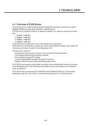
...a single chip solution that integrates the digital, mixed-signal, RF functionality and a direct-to 85C. The E-GOLDvoice supports a direct battery connection, hence eliminating the need for voice-centric Mobile Phone applications. GSM850 / GSM1900 3. The E-GOLDvoice is powered by default a low...cores. The E-GOLDvoice has different power down modes and an integrated power up sequencer. The operating temperature range from -40C to -battery Power Management Unit. E-GOLDvoice is optimized for an external Power Management Unit. GSM850 / GSM1800 2. GSM900 / GSM1800 4. The transceiver ...
...a single chip solution that integrates the digital, mixed-signal, RF functionality and a direct-to 85C. The E-GOLDvoice supports a direct battery connection, hence eliminating the need for voice-centric Mobile Phone applications. GSM850 / GSM1900 3. The E-GOLDvoice is powered by default a low...cores. The E-GOLDvoice has different power down modes and an integrated power up sequencer. The operating temperature range from -40C to -battery Power Management Unit. E-GOLDvoice is optimized for an external Power Management Unit. GSM850 / GSM1800 2. GSM900 / GSM1800 4. The transceiver ...

Service Manual
Page 16
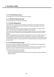
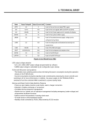
TECHNICAL BRIEF ] Mixed Signal and Power Management Unit • DC/DC boost for voltages up to 15V for driving White or Blue LEDs • 8-Ohm loud speaker driver (250/350mW) • 16-Ohm earpiece driver • 32-Ohm headset driver • 4 measurement interfaces (PA temperature, battery voltage, battery temperature,and ambient temperature) • Differential microphone input • System start up circuitry • Charger circuitry for NiCd, NiMh and LiIon cells • Integrated regulators for direct connection to battery. - 17 - 3.
TECHNICAL BRIEF ] Mixed Signal and Power Management Unit • DC/DC boost for voltages up to 15V for driving White or Blue LEDs • 8-Ohm loud speaker driver (250/350mW) • 16-Ohm earpiece driver • 32-Ohm headset driver • 4 measurement interfaces (PA temperature, battery voltage, battery temperature,and ambient temperature) • Differential microphone input • System start up circuitry • Charger circuitry for NiCd, NiMh and LiIon cells • Integrated regulators for direct connection to battery. - 17 - 3.

Service Manual
Page 18
... unit contains: • Voltage regulators for the On-chip and Off-chip functional blocks • Charger circuitry for temperature, battery technology, voltage, etc.) and a ringer buffer. TECHNICAL BRIEF 3.1.4 PMU Details The E-GOLDvoice includes battery charger support (various sensor connections for NiCd, NiMh and LiIon cells. 3.1.5 Bus Concept The E-GOLDvoice has two cores...
... unit contains: • Voltage regulators for the On-chip and Off-chip functional blocks • Charger circuitry for temperature, battery technology, voltage, etc.) and a ringer buffer. TECHNICAL BRIEF 3.1.4 PMU Details The E-GOLDvoice includes battery charger support (various sensor connections for NiCd, NiMh and LiIon cells. 3.1.5 Bus Concept The E-GOLDvoice has two cores...
Service Manual
Page 19
... The E-GOLDvoice provides the power management unit (PMU) for very a low external parts count. A charger control circuit charges NiCd, NiMH and LiIon batteries. It offers a wide charger voltage range, making halfwave/full-wave charging with IMEI and SIM-lock protection - 20 - Flash images that are not...small part is running at 32kHz and the controller RAM is directly connected to a power saving mode. The integrated PMU is switched to the battery and provides a set of the Flash code is supported with the public key. The TEAKLite ROM can be loaded. 3. The charger control ...
... The E-GOLDvoice provides the power management unit (PMU) for very a low external parts count. A charger control circuit charges NiCd, NiMH and LiIon batteries. It offers a wide charger voltage range, making halfwave/full-wave charging with IMEI and SIM-lock protection - 20 - Flash images that are not...small part is running at 32kHz and the controller RAM is directly connected to a power saving mode. The integrated PMU is switched to the battery and provides a set of the Flash code is supported with the public key. The TEAKLite ROM can be loaded. 3. The charger control ...

Service Manual
Page 22
... BRIEF RF input and output ports of the SKY77318 are internally matched to a 50 Ω load to reduce the number of PAM circuitry to minimize battery drain. - 23 -
... BRIEF RF input and output ports of the SKY77318 are internally matched to a 50 Ω load to reduce the number of PAM circuitry to minimize battery drain. - 23 -

Service Manual
Page 24
....768 kHz (32k) clock which needs to its extreme low power consumption the RTC can be switched off . Due to be fed from a small backup battery.
....768 kHz (32k) clock which needs to its extreme low power consumption the RTC can be switched off . Due to be fed from a small backup battery.

Service Manual
Page 26
... to enable, disable, and set current for driving higher current LEDs. The current sinks may be feed back from a 2.7V to maximize efficiency for small, battery-powered applications. This signal be operated individually or in parallel for each LED with 16 settings down to three channels of LCD. Data 1 2 3 4 5 6 7 8 Output (mA...
... to enable, disable, and set current for driving higher current LEDs. The current sinks may be feed back from a 2.7V to maximize efficiency for small, battery-powered applications. This signal be operated individually or in parallel for each LED with 16 settings down to three channels of LCD. Data 1 2 3 4 5 6 7 8 Output (mA...

Service Manual
Page 29
... 30 - constant voltage; and end of current from an external power source. The AAT3681A precisely regulates battery charge voltage and current for the battery charge cycle: pre-conditioning/trickle charge; The adapter/USB charge input constant current level can be programmed ...up to charge single Cell lithiumion/polymer batteries with just one external component required For complete functionality. TECHNICAL BRIEF 3.8 Battery Charging Block Interface CHARGING IC 2V8_VIO VCHARGE VBAT VCHARGE R118 NA U101 CHARGE_DETECT R119 ...
... 30 - constant voltage; and end of current from an external power source. The AAT3681A precisely regulates battery charge voltage and current for the battery charge cycle: pre-conditioning/trickle charge; The adapter/USB charge input constant current level can be programmed ...up to charge single Cell lithiumion/polymer batteries with just one external component required For complete functionality. TECHNICAL BRIEF 3.8 Battery Charging Block Interface CHARGING IC 2V8_VIO VCHARGE VBAT VCHARGE R118 NA U101 CHARGE_DETECT R119 ...

Service Manual
Page 39
... VBAT_4 VBAT_3 C115 2.2u (1608) (16V,K,X5R) The E-GOLDvoice integrated power management unit (PMU) supports direct connection to battery (DCB). The external memory and SIM card supply is the battery voltage. That means all supply voltages needed are implemented for active and idle power saving. - 40 - After system start ... integrated linear voltage regulators. Table 144 is an overview of these linear voltage regulators is provided by the on -chip with discharged batteries, trickle charging and system reset control. The input of the internal generated supply voltages. 3.
... VBAT_4 VBAT_3 C115 2.2u (1608) (16V,K,X5R) The E-GOLDvoice integrated power management unit (PMU) supports direct connection to battery (DCB). The external memory and SIM card supply is the battery voltage. That means all supply voltages needed are implemented for active and idle power saving. - 40 - After system start ... integrated linear voltage regulators. Table 144 is an overview of these linear voltage regulators is provided by the on -chip with discharged batteries, trickle charging and system reset control. The input of the internal generated supply voltages. 3.
Service Manual
Page 40
... RAM is switched off for most of the baseband module. • Standby mode controlled by VCXO_EN provided by pin configuration upon battery insertion, push button, alarm, charger connection. • Detection of battery exchange or re-insertion. • Complete start-up sequence management. • System turn-on, system turn-off operation management including...
... RAM is switched off for most of the baseband module. • Standby mode controlled by VCXO_EN provided by pin configuration upon battery insertion, push button, alarm, charger connection. • Detection of battery exchange or re-insertion. • Complete start-up sequence management. • System turn-on, system turn-off operation management including...

Service Manual
Page 53
... C110 C106 26Mhz C108 V_SIM 2.85V C107 2.8V V_IO C109 V_MEM 2.8V C101 V_BUF 3.2V LDO VOLTAGE PART C101 C107 C111 TEST POINT Check Points -Battery Voltage( Need to over 3.35V) -Power-On Key detection (PWRON signal) -Outputs of LDOs from EGV 4.3 Power On Trouble 4. TROUBLE SHOOTING - 54...
... C110 C106 26Mhz C108 V_SIM 2.85V C107 2.8V V_IO C109 V_MEM 2.8V C101 V_BUF 3.2V LDO VOLTAGE PART C101 C107 C111 TEST POINT Check Points -Battery Voltage( Need to over 3.35V) -Power-On Key detection (PWRON signal) -Outputs of LDOs from EGV 4.3 Power On Trouble 4. TROUBLE SHOOTING - 54...

Service Manual
Page 54
TROUBLE SHOOTING Power On Trouble CHECKING FLOW START Check Battery Voltage > 3.35V YES Push power-on key And check the level change of PWRKEY YES Check the voltage of The LDO outputs at U102 NO Charge or Change Battery NO Check the contact of power key Or dome-switch NO Replace U102 YES THE PHONE WILL POWER ON. LDO VOLTAGE PART V_BUF 3.2V C101 V_MEM 2.8V C109 V_IO 2.8V C107 V_SIM 2.85V C108 VRF0 1.5V C110 V_ANA 2.5V C113 - 55 - 4.
TROUBLE SHOOTING Power On Trouble CHECKING FLOW START Check Battery Voltage > 3.35V YES Push power-on key And check the level change of PWRKEY YES Check the voltage of The LDO outputs at U102 NO Charge or Change Battery NO Check the contact of power key Or dome-switch NO Replace U102 YES THE PHONE WILL POWER ON. LDO VOLTAGE PART V_BUF 3.2V C101 V_MEM 2.8V C109 V_IO 2.8V C107 V_SIM 2.85V C108 VRF0 1.5V C110 V_ANA 2.5V C113 - 55 - 4.

Service Manual
Page 73
TROUBLE SHOOTING Checking Flow Start Check the voltage level of U100.C3 = Low ? Yes Check the Signal, C117,C118 Yes Check the Level of U100 = Vbat? 4. Yes Check the Signal, L102,L103 Yes Check the Contact Of CN101 Yes Try again or Change the Board Check No The battery Check U102 No Check No U102 Re-solder No L102,L103 Re-Assemble or Re-place No Speaker - 74 -
TROUBLE SHOOTING Checking Flow Start Check the voltage level of U100.C3 = Low ? Yes Check the Signal, C117,C118 Yes Check the Level of U100 = Vbat? 4. Yes Check the Signal, L102,L103 Yes Check the Contact Of CN101 Yes Try again or Change the Board Check No The battery Check U102 No Check No U102 Re-solder No L102,L103 Re-Assemble or Re-place No Speaker - 74 -

Service Manual
Page 76
4. TROUBLE SHOOTING 4.14 Charging Trouble TEST POINT Check Points -Connection of TA (check TA voltage 5.2V) -Charging Current Path component voltage drop -Battery voltage -Charging IC R124 Charger IC U101 C125 VBAT VCHARGE =5.2V C126 CN301 CIRCUIT CHARGING IC 2V8_VIO VCHARGE VBAT VCHARGE R118 NA U101 CHARGE_DETECT R119 1....
4. TROUBLE SHOOTING 4.14 Charging Trouble TEST POINT Check Points -Connection of TA (check TA voltage 5.2V) -Charging Current Path component voltage drop -Battery voltage -Charging IC R124 Charger IC U101 C125 VBAT VCHARGE =5.2V C126 CN301 CIRCUIT CHARGING IC 2V8_VIO VCHARGE VBAT VCHARGE R118 NA U101 CHARGE_DETECT R119 1....

Service Manual
Page 77
4. NO NO LOW NO NO YES Charging is properly operating Resolder the CN300 Pin 12,13 : VCHARGE The TA is charged? YES Is The Voltage of order Change the TA Replace the U101 Check the U102 The battery may have problems. Change the battery. - 78 - YES Battery is out of C126 5.2V ? TROUBLE SHOOTING Checking Flow START I/O Connector(CN301) Is well-soldered ? YES The Voltage of C128 Is 2.8V YES Check the voltage of R124 High or Low?
4. NO NO LOW NO NO YES Charging is properly operating Resolder the CN300 Pin 12,13 : VCHARGE The TA is charged? YES Is The Voltage of order Change the TA Replace the U101 Check the U102 The battery may have problems. Change the battery. - 78 - YES Battery is out of C126 5.2V ? TROUBLE SHOOTING Checking Flow START I/O Connector(CN301) Is well-soldered ? YES The Voltage of C128 Is 2.8V YES Check the voltage of R124 High or Low?
Service Manual
Page 95
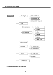
Backlight 2. LCD Color 2. Auto LCD 4. Vibrator On 2. 9. Backlight On 2. Green 3. Audio * 6. Backlight Off 3. Battery Info 1. Black 5. Audio Test 2. Red 2. FM Radio 1. Blue 4. Vibrator 1. Close * FM Radio function is not supported - 96 - LCD 1. Contrast 3. White 6. Backlight Value 1. ENGINEERING MODE BB TEST 1. Vibrator Off 5.
Backlight 2. LCD Color 2. Auto LCD 4. Vibrator On 2. 9. Backlight On 2. Green 3. Audio * 6. Backlight Off 3. Battery Info 1. Black 5. Audio Test 2. Red 2. FM Radio 1. Blue 4. Vibrator 1. Close * FM Radio function is not supported - 96 - LCD 1. Contrast 3. White 6. Backlight Value 1. ENGINEERING MODE BB TEST 1. Vibrator Off 5.

