Owners Manual
Page 6
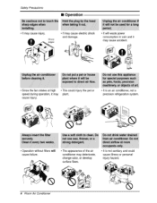
... _,uld iniury the _t or sp.e_ during operation, it:may deteriorate, change color, or develop s.ufface flaws. ., It is an air _nditioner, not a precision refrigeration system . m Operation , It may cause injury. • It may cause electric shock and damage. ., it will cause failure.. • Tlhe ap_arance of the air condffi...
... _,uld iniury the _t or sp.e_ during operation, it:may deteriorate, change color, or develop s.ufface flaws. ., It is an air _nditioner, not a precision refrigeration system . m Operation , It may cause injury. • It may cause electric shock and damage. ., it will cause failure.. • Tlhe ap_arance of the air condffi...
Service Manual
Page 2
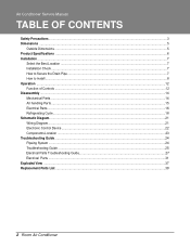
... Secure the Drain Pipe ...7 How to Install...8 Operation ...12 Function of Controls ...12 Disassembly ...14 Mechanical Parts...14 Air handling Parts...15 Electrical Parts ...16 Refrigerating Cycle...18 Schematic Diagram...21 Wiring Diagram...21 Electronic Control Device ...22 Components Location ...23 Troubleshooting Guide ...24 Pipeing System ...24 Troubleshooting Guide ...25 Electrical...
... Secure the Drain Pipe ...7 How to Install...8 Operation ...12 Function of Controls ...12 Disassembly ...14 Mechanical Parts...14 Air handling Parts...15 Electrical Parts ...16 Refrigerating Cycle...18 Schematic Diagram...21 Wiring Diagram...21 Electronic Control Device ...22 Components Location ...23 Troubleshooting Guide ...24 Pipeing System ...24 Troubleshooting Guide ...25 Electrical...

Service Manual
Page 6
...CONSTRUCTION PROTECTOR POWER CORD COMPRESSOR FAN MOTOR DRAIN SYSTEM NET WEIGHT OUTSIDE DIMENSION (W x H x D) (lbs/kg) (inch) (mm) HBLG8003R LB8000ER LW8000ER 1ø, 115, 60Hz HBLG1003R LWHD1006R(Y6) L1006R(Y6) 8 ,000 8 ,2 00 10, 000 8 20 750 1 ,020 7.4 7.0 9.2 9.8 10 . 9 9 .8 26.7(DB)* 19.4(WB)** ... COOLING CAPACITY (Btu/h) INPUT (W) RUNNING CURRENT E.E.R OPERATING CONDITION (A) (BTU/W .h) INDOOR (°C) OUTDOOR (°C) REFRIGERANT (R-22) CHARGE EVAPORATOR CONDENSER FAN, INDOOR FAN, OUTDOOR FAN SPEEDS, FAN/COOLING FAN MOTOR OPERATION CONTROL ROOM TEMP.
...CONSTRUCTION PROTECTOR POWER CORD COMPRESSOR FAN MOTOR DRAIN SYSTEM NET WEIGHT OUTSIDE DIMENSION (W x H x D) (lbs/kg) (inch) (mm) HBLG8003R LB8000ER LW8000ER 1ø, 115, 60Hz HBLG1003R LWHD1006R(Y6) L1006R(Y6) 8 ,000 8 ,2 00 10, 000 8 20 750 1 ,020 7.4 7.0 9.2 9.8 10 . 9 9 .8 26.7(DB)* 19.4(WB)** ... COOLING CAPACITY (Btu/h) INPUT (W) RUNNING CURRENT E.E.R OPERATING CONDITION (A) (BTU/W .h) INDOOR (°C) OUTDOOR (°C) REFRIGERANT (R-22) CHARGE EVAPORATOR CONDENSER FAN, INDOOR FAN, OUTDOOR FAN SPEEDS, FAN/COOLING FAN MOTOR OPERATION CONTROL ROOM TEMP.
Service Manual
Page 16
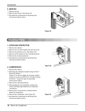
... no valve to the removal procedure, above . Disassembly 6. SHROUD 1. Remove the fan. 2. Remove the terminal cover. (See Figure 24) 4. Remove the overload protector. 6. Discharge the refrigerant system using a FreonTM Recovery System. After purging the unit completely, unbraze the suction and discharge tubes at the compressor connections. 5. Remove the compressor. (See Figure...
... no valve to the removal procedure, above . Disassembly 6. SHROUD 1. Remove the fan. 2. Remove the terminal cover. (See Figure 24) 4. Remove the overload protector. 6. Discharge the refrigerant system using a FreonTM Recovery System. After purging the unit completely, unbraze the suction and discharge tubes at the compressor connections. 5. Remove the compressor. (See Figure...
Service Manual
Page 18
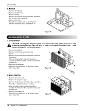
... which fasten the brace. 3. Remove the evaporator. 7. Remove the cabinet. 2. CONDENSER CAUTION: Discharge the refrigerant system using a FreonTM Recovery System. After discharging the refrigerant completely, unbraze the interconnecting tube at the condenser connections. 5. Remove the 5 screws which fasten the evaporator... and shroud. 4. If there is no valve to notes. (See Figure 29) Figure 29 2. After discharging the refrigerant completely, unbraze the interconnecting tube at the evaporator connections. 6. Remove the air guide upper. 3. Re-install the components...
... which fasten the brace. 3. Remove the evaporator. 7. Remove the cabinet. 2. CONDENSER CAUTION: Discharge the refrigerant system using a FreonTM Recovery System. After discharging the refrigerant completely, unbraze the interconnecting tube at the condenser connections. 5. Remove the 5 screws which fasten the evaporator... and shroud. 4. If there is no valve to notes. (See Figure 29) Figure 29 2. After discharging the refrigerant completely, unbraze the interconnecting tube at the evaporator connections. 6. Remove the air guide upper. 3. Re-install the components...

Service Manual
Page 19
...valves A and B closed . 4) If more charge is in place after servicing the system. 2. See figure 31B. Do not add the liquid refrigerant to attach the recovery system, install one (such as shown in the system. allow pressure to enter the system. d. Solder the pinch-off tool... , discharge the hose at the manifold connection. 3) Open valve A and allow it on to 30 lbs. Service Manual 19 After discharging the refrigerant completely, unbraze the interconnecting tube at the manifold connection. 5) The system is obtained. Re-install the components by referring to valve C by means...
...valves A and B closed . 4) If more charge is in place after servicing the system. 2. See figure 31B. Do not add the liquid refrigerant to attach the recovery system, install one (such as shown in the system. allow pressure to enter the system. d. Solder the pinch-off tool... , discharge the hose at the manifold connection. 3) Open valve A and allow it on to 30 lbs. Service Manual 19 After discharging the refrigerant completely, unbraze the interconnecting tube at the manifold connection. 5) The system is obtained. Re-install the components by referring to valve C by means...
Service Manual
Page 24
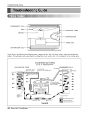
...COIL FAN MOTOR EVAPORATOR COIL CAPILLARY TUBE COMPRESSOR TURBO FAN Figure 32 is a brief description of the refrigerant in what is called the refrigeration system. This will help you to understand the refrigeration cycle and the flow of the important components and their function in the cooling cycle. ROOM AIR ...CONITIONER CYCLE OF REFRIGERATION EVAPORATOR COILS COOLED AIR COMPLETE LIQUID BOIL OFF POINT SUCTION LINE COOL LOW PRESSURE VAPOR ROOM AIR HEAT LOAD CONDENSER COILS VAPOR ...
...COIL FAN MOTOR EVAPORATOR COIL CAPILLARY TUBE COMPRESSOR TURBO FAN Figure 32 is a brief description of the refrigerant in what is called the refrigeration system. This will help you to understand the refrigeration cycle and the flow of the important components and their function in the cooling cycle. ROOM AIR ...CONITIONER CYCLE OF REFRIGERATION EVAPORATOR COILS COOLED AIR COMPLETE LIQUID BOIL OFF POINT SUCTION LINE COOL LOW PRESSURE VAPOR ROOM AIR HEAT LOAD CONDENSER COILS VAPOR ...

Service Manual
Page 25
... Check heat load increase. Clean condenser. Adjusting of compressor. Check clogging in refrigeration circuit. Satisfactory operation with temperature difference of inlet & outlet air ; 44~50°F(7~10°C) Replacement of refrigerant charged. The one is called Starting Failure which is caused from an electrical ...filter. Unit runs but poor cooling. Check gas leakage. Check inside gas pressure. Repair clogging in refrigeration circuit. Troubleshooting Guide Troubleshooting Guide In general, possible trouble is ineffective Air Conditioning caused by a defect in the...
... Check heat load increase. Clean condenser. Adjusting of compressor. Check clogging in refrigeration circuit. Satisfactory operation with temperature difference of inlet & outlet air ; 44~50°F(7~10°C) Replacement of refrigerant charged. The one is called Starting Failure which is caused from an electrical ...filter. Unit runs but poor cooling. Check gas leakage. Check inside gas pressure. Repair clogging in refrigeration circuit. Troubleshooting Guide Troubleshooting Guide In general, possible trouble is ineffective Air Conditioning caused by a defect in the...

Service Manual
Page 36
Insufficient cooling or heating Capacitor Wiring Refrigerating system Air filter Exhaust damper door Unit undersized Excessive noise Turbo or fan Copper tubing Check the TEMP control. Replace the thermistor if the circuit ...
Insufficient cooling or heating Capacitor Wiring Refrigerating system Air filter Exhaust damper door Unit undersized Excessive noise Turbo or fan Copper tubing Check the TEMP control. Replace the thermistor if the circuit ...
