
Owners Manual
Page 7
...use this manual. Injuries ,can destroy the insulation, leading to clean inside the air conditioner. They should be written on while cleaning inner parts of the unit. When cleaning the unit, first make sure that the power and breaker are turned off. preserving precision devices, food, peR... 2i_Due to the possibility of injury if the unit's power is damaged and requires, replacement, have an Authorized Servicer install an exact replacement part. 1 Being exposed to direct airflow for .an extended period o,f time could b,e i_ hazardous to your model number and serial number available...
...use this manual. Injuries ,can destroy the insulation, leading to clean inside the air conditioner. They should be written on while cleaning inner parts of the unit. When cleaning the unit, first make sure that the power and breaker are turned off. preserving precision devices, food, peR... 2i_Due to the possibility of injury if the unit's power is damaged and requires, replacement, have an Authorized Servicer install an exact replacement part. 1 Being exposed to direct airflow for .an extended period o,f time could b,e i_ hazardous to your model number and serial number available...

Owners Manual
Page 47
LG Electronics will repair or at its option replace, without charge, your product which proves to be defective in material or workmanship under normal use, during the warranty period as long as explaining the operation of purchase. WARRANTY PERIOD: Labor: Parts: 5 Years 5 Years Compressor: 5 Years HOW ... Copy of original purchase. Press the appropriate option, and please have your product type (AIR CONDITIONER), and ZIP/postal code ready. LG ELECTRONICS SHALL NOT BE LIABLE FOR THE LOSS OF THE USE OF THE PRODUCT, INCONVENIENCE, LOSS OR ANY OTHER DAMAGES, DIRECT OR ...
LG Electronics will repair or at its option replace, without charge, your product which proves to be defective in material or workmanship under normal use, during the warranty period as long as explaining the operation of purchase. WARRANTY PERIOD: Labor: Parts: 5 Years 5 Years Compressor: 5 Years HOW ... Copy of original purchase. Press the appropriate option, and please have your product type (AIR CONDITIONER), and ZIP/postal code ready. LG ELECTRONICS SHALL NOT BE LIABLE FOR THE LOSS OF THE USE OF THE PRODUCT, INCONVENIENCE, LOSS OR ANY OTHER DAMAGES, DIRECT OR ...
Service Manual
Page 2
... Best Location ...7 Installation Check ...7 How to Secure the Drain Pipe ...7 How to Install...8 Operation ...12 Function of Controls ...12 Disassembly ...14 Mechanical Parts...14 Air handling Parts...15 Electrical Parts ...16 Refrigerating Cycle...18 Schematic Diagram...21 Wiring Diagram...21 Electronic Control Device ...22 Components Location ...23 Troubleshooting Guide ...24 Pipeing System ...24...
... Best Location ...7 Installation Check ...7 How to Secure the Drain Pipe ...7 How to Install...8 Operation ...12 Function of Controls ...12 Disassembly ...14 Mechanical Parts...14 Air handling Parts...15 Electrical Parts ...16 Refrigerating Cycle...18 Schematic Diagram...21 Wiring Diagram...21 Electronic Control Device ...22 Components Location ...23 Troubleshooting Guide ...24 Pipeing System ...24...

Service Manual
Page 3
...; Doing so may cause electric shock or fire due to an explosion or fire. Incorrect operation due to avoid a hazard. (Y attachment) Always plug into electric parts. • Doing so may cause failure of machine or electric shock. WWAARRNNIINNGG Plug in order to ignoring instructions might cause harm or damage, the seriousness...
...; Doing so may cause electric shock or fire due to an explosion or fire. Incorrect operation due to avoid a hazard. (Y attachment) Always plug into electric parts. • Doing so may cause failure of machine or electric shock. WWAARRNNIINNGG Plug in order to ignoring instructions might cause harm or damage, the seriousness...

Service Manual
Page 4
.... • Operating the air conditioner in the presence of a stove, etc. • An oxygen shortage may cause failure of appliance. CCAAUUTTIIOONN Never touch the metal parts of gas • Doing so may cause electric shock or damage. Ensure that the cord is off the the power switch of the main body...
.... • Operating the air conditioner in the presence of a stove, etc. • An oxygen shortage may cause failure of appliance. CCAAUUTTIIOONN Never touch the metal parts of gas • Doing so may cause electric shock or damage. Ensure that the cord is off the the power switch of the main body...

Service Manual
Page 8
... F JH A COOL FAN DRY HEAT DEFROST FAN INDOOR DESIRED ENERGY SAVER AIR PURYFIER AUTO RESTART RIGHT SIDE B HORIZONTAL LINE 1. WHEN USING INSTALLATION KITS A. NAME OF PARTS 1 FRAME CURTAIN 2 SILL SUPPORT 3 BOLT 4 NUT 5 SCREW(TYPE A) 6 SCREW(TYPE B) 7 SCREW(TYPE C) 8 FOAM-STRIP 9 FOAM-PE 10 UPPER GUIDE 11 FOAM-PE 12 FRAME GUIDE...
... F JH A COOL FAN DRY HEAT DEFROST FAN INDOOR DESIRED ENERGY SAVER AIR PURYFIER AUTO RESTART RIGHT SIDE B HORIZONTAL LINE 1. WHEN USING INSTALLATION KITS A. NAME OF PARTS 1 FRAME CURTAIN 2 SILL SUPPORT 3 BOLT 4 NUT 5 SCREW(TYPE A) 6 SCREW(TYPE B) 7 SCREW(TYPE C) 8 FOAM-STRIP 9 FOAM-PE 10 UPPER GUIDE 11 FOAM-PE 12 FRAME GUIDE...

Service Manual
Page 10
... Screw(Type B) 6 Figure 8 9. Attach the sill support to the cabinet track hole in relation to each Frame Curtain to the window stool by using the parts in each support (See Figure 7).
... Screw(Type B) 6 Figure 8 9. Attach the sill support to the cabinet track hole in relation to each Frame Curtain to the window stool by using the parts in each support (See Figure 7).

Service Manual
Page 14
Mechanical Parts 1. Pull the base pan forward. (See Figure 17) 4. Figure 16 3. Remove the cabinet. 3. Remove the housing which fasten the cabinet at both sides. 2. Remove the ...
Mechanical Parts 1. Pull the base pan forward. (See Figure 17) 4. Figure 16 3. Remove the cabinet. 3. Remove the housing which fasten the cabinet at both sides. 2. Remove the ...

Service Manual
Page 15
... and pulling it . (See Figure 21) 11. Remove the 5 screws which fasten the brace. 5. Re-install by referring to the removal procedure, above. Air Handling Parts 4. AIR GUIDE AND TURBO FAN 1. Move the air guide backward, and pull out from the base pan. 14. Remove the brace. 3. Remove the fan. (See...
... and pulling it . (See Figure 21) 11. Remove the 5 screws which fasten the brace. 5. Re-install by referring to the removal procedure, above. Air Handling Parts 4. AIR GUIDE AND TURBO FAN 1. Move the air guide backward, and pull out from the base pan. 14. Remove the brace. 3. Remove the fan. (See...
Service Manual
Page 16
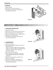
...) 3. Re-install the components by referring to attach the recovery system, install one (such as a WATCO A-1) before venting the FreonTM. Disassembly 6. SHROUD 1. Figure 23 Electrical Parts 1. Remove the 3 nuts and the 3 washers which fastens the terminal cover. 3. Remove the fan. 2. Remove the terminal cover. (See Figure 24) 4. COMPRESSOR 1. Leave the valve...
...) 3. Re-install the components by referring to attach the recovery system, install one (such as a WATCO A-1) before venting the FreonTM. Disassembly 6. SHROUD 1. Figure 23 Electrical Parts 1. Remove the 3 nuts and the 3 washers which fastens the terminal cover. 3. Remove the fan. 2. Remove the terminal cover. (See Figure 24) 4. COMPRESSOR 1. Leave the valve...

Service Manual
Page 22
ASSEMBLY BK RD 3 COMP. DESCRIPTION 1 MOTOR ASSY 2 CAPACITOR 3 COMPRESSOR 4 OVERLOAD PROTECTOR 5 DC PCB ASSEMBLY 6 AC PCB ASSEMBLY 7 THERMISTOR 8 PLASMA FILTER ASSY S: Service Parts N: Non Service Parts Q'TY PER SET REMARKS 1 S 1 S 1 S 1 S 1 S 1 S 1 S 1 S 22 Room Air Conditioner S C BL AC PCB ASSEMBLY 8 4 OLP WIRING DIAGRAM AIR FILTER ASSEMBLY LOCATION NO. Schematic Diagram Wiring Diagram 1 BK ...
ASSEMBLY BK RD 3 COMP. DESCRIPTION 1 MOTOR ASSY 2 CAPACITOR 3 COMPRESSOR 4 OVERLOAD PROTECTOR 5 DC PCB ASSEMBLY 6 AC PCB ASSEMBLY 7 THERMISTOR 8 PLASMA FILTER ASSY S: Service Parts N: Non Service Parts Q'TY PER SET REMARKS 1 S 1 S 1 S 1 S 1 S 1 S 1 S 1 S 22 Room Air Conditioner S C BL AC PCB ASSEMBLY 8 4 OLP WIRING DIAGRAM AIR FILTER ASSEMBLY LOCATION NO. Schematic Diagram Wiring Diagram 1 BK ...

Service Manual
Page 27
Electrical Parts Troubleshooting Guide Troubleshooting Guide Possible Trouble 1 The unit does not operate. output? Is the reset circuit good? NO (The No.14 of IC02D NO DC ...
Electrical Parts Troubleshooting Guide Troubleshooting Guide Possible Trouble 1 The unit does not operate. output? Is the reset circuit good? NO (The No.14 of IC02D NO DC ...

Service Manual
Page 31
... the NO Trans input power AC 115V? NO • Check the AC PCB pattern. YES Replace AC PCB Ass'y. • Check the PCB pattern. Electrical Parts Troubleshooting Guide Possible Trouble 1 The unit does not operate. YES ••CChheecckktthheeFFuussee.. ••CChheecckkththeewwiriirninggddiaiaggraramm. . NO Is the voltage No.40 of Micom is...
... the NO Trans input power AC 115V? NO • Check the AC PCB pattern. YES Replace AC PCB Ass'y. • Check the PCB pattern. Electrical Parts Troubleshooting Guide Possible Trouble 1 The unit does not operate. YES ••CChheecckktthheeFFuussee.. ••CChheecckkththeewwiriirninggddiaiaggraramm. . NO Is the voltage No.40 of Micom is...

Service Manual
Page 36
... with a vacuum cleaner (do not damage fins) or brush. Check the terminals. If the turbo or fan is hitting air guide, rearrange the air handling parts. If open . Check the set TEMP control to be cooled. Thermistor Capacitor (Discharge capacitor before reassembling. Voltage Overload Compressor cycles on overload. If condenser fins...
... with a vacuum cleaner (do not damage fins) or brush. Check the terminals. If the turbo or fan is hitting air guide, rearrange the air handling parts. If open . Check the set TEMP control to be cooled. Thermistor Capacitor (Discharge capacitor before reassembling. Voltage Overload Compressor cycles on overload. If condenser fins...

Service Manual
Page 39
DESCRIPTION PART NO. LWHD1006R L1006R REMARK LWHD1006RY6 130410 130910 BASE ASSEMBLY,WELD[SINGLE] CABINET ASSEMBLY,SINGLE 3041A20021N 3041A20021V 3041A20021V R 3091AR2317M 3091AR2317M 3091AR2317M R 135312 GRILLE ASSEMBLY,FRONT(SINGLE) ... R TBZ30826701 2520UCDK004 2520UCDK004 R 5900AR1167B 5900AR1167B 5900AR1167B R 5900A20020A 5900A20020A 5900A20020A R 6711A20034G 6711A20034G 6711A20034G R 3H02932B 3H02932B 3H02932B R W0CZZ CAPACITOR, DRAWING 2H01451M 0CZZA20001N 0CZZA20001N R Service Manual 39 Replacement Parts List Replacement Parts List LOCATION NO.
DESCRIPTION PART NO. LWHD1006R L1006R REMARK LWHD1006RY6 130410 130910 BASE ASSEMBLY,WELD[SINGLE] CABINET ASSEMBLY,SINGLE 3041A20021N 3041A20021V 3041A20021V R 3091AR2317M 3091AR2317M 3091AR2317M R 135312 GRILLE ASSEMBLY,FRONT(SINGLE) ... R TBZ30826701 2520UCDK004 2520UCDK004 R 5900AR1167B 5900AR1167B 5900AR1167B R 5900A20020A 5900A20020A 5900A20020A R 6711A20034G 6711A20034G 6711A20034G R 3H02932B 3H02932B 3H02932B R W0CZZ CAPACITOR, DRAWING 2H01451M 0CZZA20001N 0CZZA20001N R Service Manual 39 Replacement Parts List Replacement Parts List LOCATION NO.

Service Manual
Page 40
... 3720A10111C 4995A11014A 6871A20417C 3831A10021L 6871A20418A 6323A20004P 6411A20056E 4681A20069H 4900A20003A 4948A10014A 5211A20470L 5211A21786A 5211A10074J 5211A30275M 5239A20012A 5421A10026P ACG32514902 4830AR4335A 2520UCDK004 5900AR1167B 5900A20020A 6711A20034G 3H02932B 0CZZA20001N Replacement Parts List REMARK R R R R R R R R R R R R R R R R R R R R R R R R R R R R R R R R R R R R R Service Manual 40 DESCRIPTION 130410 130910 135312 135313 135500 147581 147582-1 147582-2 148000 159980 152302 237200 249950 268712 238310 268714 263230 264110 346811...
... 3720A10111C 4995A11014A 6871A20417C 3831A10021L 6871A20418A 6323A20004P 6411A20056E 4681A20069H 4900A20003A 4948A10014A 5211A20470L 5211A21786A 5211A10074J 5211A30275M 5239A20012A 5421A10026P ACG32514902 4830AR4335A 2520UCDK004 5900AR1167B 5900A20020A 6711A20034G 3H02932B 0CZZA20001N Replacement Parts List REMARK R R R R R R R R R R R R R R R R R R R R R R R R R R R R R R R R R R R R R Service Manual 40 DESCRIPTION 130410 130910 135312 135313 135500 147581 147582-1 147582-2 148000 159980 152302 237200 249950 268712 238310 268714 263230 264110 346811...


