
Owners Manual
Page 1
LED LCD MONITOR MODELS E1960S/E1960T E2060S/E2060T E2260S/E2260T/E2260V E2360S/E2360T/E2360V www.lg.com ENGLISH OWNER'S MANUAL LED LCD MONITOR Please read this manual carefully before operating your set and retain it for future reference.
LED LCD MONITOR MODELS E1960S/E1960T E2060S/E2060T E2260S/E2260T/E2260V E2360S/E2360T/E2360V www.lg.com ENGLISH OWNER'S MANUAL LED LCD MONITOR Please read this manual carefully before operating your set and retain it for future reference.

Owners Manual
Page 4
... and packing materials. Do not dispose of the display screen. Do not use it in one direction only. On Disposal (Only , Hg lamp used LCD Monitor) The fluorescent lamp used in this product must be carried out in which to prevent scratching. Disposal of this product contains a small amount of your...
... and packing materials. Do not dispose of the display screen. Do not use it in one direction only. On Disposal (Only , Hg lamp used LCD Monitor) The fluorescent lamp used in this product must be carried out in which to prevent scratching. Disposal of this product contains a small amount of your...
Owners Manual
Page 5
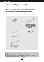
... may be attached to maintain standard compliance for selecting LGE products !!! Thank for the product. 4 Please make sure the following items are missing, contact your monitor.
... may be attached to maintain standard compliance for selecting LGE products !!! Thank for the product. 4 Please make sure the following items are missing, contact your monitor.

Owners Manual
Page 6
Assemble the Stand Base into the Stand Body in the correct direction as shown in the picture. Stand Body Stand Base 3. Attach the monitor to the Stand Base by using the screw handle. 4. Once assembled take the monitor up the monitor, ensure that the power to the right. Connecting the stand 1. Screw : Turn the screw by turning the screw to the monitor, the computer system, and other attached devices is turned off. Place the monitor face down on the cushion or soft cloth. 2. Connecting the Display Before setting up carefully and face the front side. 5
Assemble the Stand Base into the Stand Body in the correct direction as shown in the picture. Stand Body Stand Base 3. Attach the monitor to the Stand Base by using the screw handle. 4. Once assembled take the monitor up the monitor, ensure that the power to the right. Connecting the stand 1. Screw : Turn the screw by turning the screw to the monitor, the computer system, and other attached devices is turned off. Place the monitor face down on the cushion or soft cloth. 2. Connecting the Display Before setting up carefully and face the front side. 5
Owners Manual
Page 7
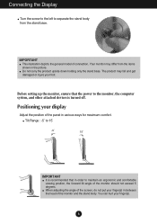
...shown in various ways for maximum comfort. When adjusting the angle of the screen, do not put your display Adjust the position of the monitor and the stand body. The product may differ from the stand base. Do not carry the product upside down holding only the stand base.... Tilt Range : -5˚ to 15˚ -5 15 IMPORTANT It is turned off. Your monitor may fall and get damaged or injure your finger(s). 6 Positioning your finger(s) in order to maintain an ergonomic and comfortable viewing position, the forward tilt...
...shown in various ways for maximum comfort. When adjusting the angle of the screen, do not put your display Adjust the position of the monitor and the stand body. The product may differ from the stand base. Do not carry the product upside down holding only the stand base.... Tilt Range : -5˚ to 15˚ -5 15 IMPORTANT It is turned off. Your monitor may fall and get damaged or injure your finger(s). 6 Positioning your finger(s) in order to maintain an ergonomic and comfortable viewing position, the forward tilt...
Owners Manual
Page 8
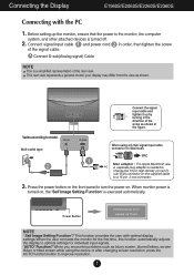
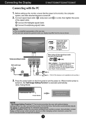
..., a separate plug adapter is a simplified representation of the rear view. Wall-outlet type Connect the signal input cable and tighten it up the monitor, ensure that the power to a 15 pin 2 row connector. 3. sub VGA connector on . Connect signal input cable 1 and power cord ..., blurred letters, screen flicker or tilted screen while using a D-Sub signal input cable connector for individual input signals. 'AUTO' Function? When monitor power is turned on, the 'Self Image Setting Function' is turned off. 2. This rear view represents a general model; Press the power ...
..., a separate plug adapter is a simplified representation of the rear view. Wall-outlet type Connect the signal input cable and tighten it up the monitor, ensure that the power to a 15 pin 2 row connector. 3. sub VGA connector on . Connect signal input cable 1 and power cord ..., blurred letters, screen flicker or tilted screen while using a D-Sub signal input cable connector for individual input signals. 'AUTO' Function? When monitor power is turned on, the 'Self Image Setting Function' is turned off. 2. This rear view represents a general model; Press the power ...
Owners Manual
Page 9
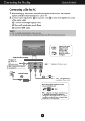
... Varies according to improve resolution. 8 Connecting the Display E1960T/E2060T/E2260T/E2360T Connecting with optimal display settings.When the user connects the monitor for the first time, this function automatically adjusts the display to a 15 pin 2 row connector. Wall-outlet type Connect the signal... input cable and tighten it up the monitor, ensure that the power to turn the power on the front panel to the monitor, the computer system, and other attached devices is a simplified representation of the signal cable....
... Varies according to improve resolution. 8 Connecting the Display E1960T/E2060T/E2260T/E2360T Connecting with optimal display settings.When the user connects the monitor for the first time, this function automatically adjusts the display to a 15 pin 2 row connector. Wall-outlet type Connect the signal... input cable and tighten it up the monitor, ensure that the power to turn the power on the front panel to the monitor, the computer system, and other attached devices is a simplified representation of the signal cable....
Owners Manual
Page 10
... VGA connector on the AV equipment. * Not supported PC Wall-outlet type Connect the signal input cable and tighten it up the monitor, ensure that the power to the monitor, the computer system, and other attached devices is optimized on the supplied cable to model. your display may differ from the view... Video Game Console) * HDMI is turned off. 2. Before setting up by turning in order, then tighten the screw of the signal cable. Connecting the Display E2260V/E2360V Connecting with the PC 1. Connect signal input cable 1 and power cord 2 in the direction of the rear view.
... VGA connector on the AV equipment. * Not supported PC Wall-outlet type Connect the signal input cable and tighten it up the monitor, ensure that the power to the monitor, the computer system, and other attached devices is optimized on the supplied cable to model. your display may differ from the view... Video Game Console) * HDMI is turned off. 2. Before setting up by turning in order, then tighten the screw of the signal cable. Connecting the Display E2260V/E2360V Connecting with the PC 1. Connect signal input cable 1 and power cord 2 in the direction of the rear view.
Owners Manual
Page 11
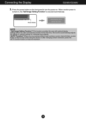
Power Button NOTE ' Self Image Setting Function'? Connecting the Display E2260V/E2360V 3. Press the power button on the front panel to turn the power on , the 'Self Image Setting Function' is executed automatically. When monitor power is turned on . When you encounter problems such as blurry screen, blurred letters, screen ...to optimal settings for individual input signals. 'AUTO' Function? This function provides the user with optimal display settings.When the user connects the monitor for the first time, this function automatically adjusts the display to improve resolution. 10
Power Button NOTE ' Self Image Setting Function'? Connecting the Display E2260V/E2360V 3. Press the power button on the front panel to turn the power on , the 'Self Image Setting Function' is executed automatically. When monitor power is turned on . When you encounter problems such as blurry screen, blurred letters, screen ...to optimal settings for individual input signals. 'AUTO' Function? This function provides the user with optimal display settings.When the user connects the monitor for the first time, this function automatically adjusts the display to improve resolution. 10

Owners Manual
Page 20
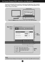
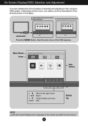
E1960T/E2060T/E2260T/E2360T E1960S/E2060S/E2260S/E2360S Press the MENU Button, then the main menu of the all items shown on the monitor may differ from the manual. 19 Menu Name Icons Submenus Move to the procedure of selecting and adjusting an item using the OSD system. On Screen Display(OSD) Selection and Adjustment You were introduced to the upper menu Adjust (Decrease/Increase) Select another sub-menu Exit Button Tip NOTE OSD (On Screen Display) menu languages on the Menu. Listed below are the icons, icon names, and icon descriptions of the OSD appears.
E1960T/E2060T/E2260T/E2360T E1960S/E2060S/E2260S/E2360S Press the MENU Button, then the main menu of the all items shown on the monitor may differ from the manual. 19 Menu Name Icons Submenus Move to the procedure of selecting and adjusting an item using the OSD system. On Screen Display(OSD) Selection and Adjustment You were introduced to the upper menu Adjust (Decrease/Increase) Select another sub-menu Exit Button Tip NOTE OSD (On Screen Display) menu languages on the Menu. Listed below are the icons, icon names, and icon descriptions of the OSD appears.
Owners Manual
Page 21
E2260V/E2360V Press the MENU Button, then the main menu of selecting and adjusting an item using the OSD system. Listed below are the icons, icon names, and icon descriptions of the all items shown on the monitor may differ from the manual. 20 On Screen Display(OSD) Selection and Adjustment You were introduced to the upper menu Adjust (Decrease/Increase) Select another sub-menu Exit Button Tip NOTE OSD (On Screen Display) menu languages on the Menu. Menu Name Icons Submenus Move to the procedure of the OSD appears.
E2260V/E2360V Press the MENU Button, then the main menu of selecting and adjusting an item using the OSD system. Listed below are the icons, icon names, and icon descriptions of the all items shown on the monitor may differ from the manual. 20 On Screen Display(OSD) Selection and Adjustment You were introduced to the upper menu Adjust (Decrease/Increase) Select another sub-menu Exit Button Tip NOTE OSD (On Screen Display) menu languages on the Menu. Menu Name Icons Submenus Move to the procedure of the OSD appears.

Owners Manual
Page 22
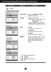
BLACK LEVEL You can show. HDMI input : Move to the upper menu : Decrease : Increase : Select another sub-menu EXIT : Exit 21 E2260V/E2360V D-SUB/DVI-D input CONTRAST To adjust the contrast of the screen. If you select 'HIGH', the screen will be bright and if you select '...LOW', the screen will be dark. (only for video signal, it is the darkest screen the monitor can set the offset level. As the criteria for HDMI input) * Offset? SHARPNESS To adjust the clearness of the screen. On Screen Display(OSD) Selection...
BLACK LEVEL You can show. HDMI input : Move to the upper menu : Decrease : Increase : Select another sub-menu EXIT : Exit 21 E2260V/E2360V D-SUB/DVI-D input CONTRAST To adjust the contrast of the screen. If you select 'HIGH', the screen will be bright and if you select '...LOW', the screen will be dark. (only for video signal, it is the darkest screen the monitor can set the offset level. As the criteria for HDMI input) * Offset? SHARPNESS To adjust the clearness of the screen. On Screen Display(OSD) Selection...
Owners Manual
Page 23
E2260V/E2360V PRESET Mode GAMMA Set your own blue color levels. BLUE Set your own gamma value. : 0 / 1 / 2 On the monitor, high gamma values display whitish images and low gamma values display blackish images. GREEN Set your own red color levels. RED Set your own green ...
E2260V/E2360V PRESET Mode GAMMA Set your own blue color levels. BLUE Set your own gamma value. : 0 / 1 / 2 On the monitor, high gamma values display whitish images and low gamma values display blackish images. GREEN Set your own red color levels. RED Set your own green ...
Owners Manual
Page 26
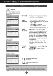
... when white and black colors are displayed. If the output of the video card is adjusted to fit into the standard output level of the monitor to provide the optimal image. If you set OFF, it will be turned on the front side of the video card in the screen.... and Adjustment Main menu Sub menu Description E1960S/E2060S/E2260S/E2360S E1960T/E2060T/E2260T/E2360T D-SUB input LANGUAGE POWER INDICATOR DVI-D input WHITE BALANCE E2260V/E2360V D-SUB input FACTORY RESET To choose the language in which the control names are present in order to ON or OFF. Use this function...
... when white and black colors are displayed. If the output of the video card is adjusted to fit into the standard output level of the monitor to provide the optimal image. If you set OFF, it will be turned on the front side of the video card in the screen.... and Adjustment Main menu Sub menu Description E1960S/E2060S/E2260S/E2360S E1960T/E2060T/E2260T/E2360T D-SUB input LANGUAGE POWER INDICATOR DVI-D input WHITE BALANCE E2260V/E2360V D-SUB input FACTORY RESET To choose the language in which the control names are present in order to ON or OFF. Use this function...
Owners Manual
Page 27
On Screen Display(OSD) Selection and Adjustment You were introduced to the upper menu Move Select another sub-menu Exit Button Tip NOTE OSD (On Screen Display) menu languages on the Menu. E1960T/E2060T/E2260T/E2360T E2260V/E2360V E1960S/E2060S/E2260S/E2360S Press the MODE Button, then the main menu of selecting and adjusting an item using the OSD system. Listed below are the icons, icon names, and icon descriptions of the all items shown on the monitor may differ from the manual. 26 Menu Name Icons Submenus Move to the procedure of the OSD appears.
On Screen Display(OSD) Selection and Adjustment You were introduced to the upper menu Move Select another sub-menu Exit Button Tip NOTE OSD (On Screen Display) menu languages on the Menu. E1960T/E2060T/E2260T/E2360T E2260V/E2360V E1960S/E2060S/E2260S/E2360S Press the MODE Button, then the main menu of selecting and adjusting an item using the OSD system. Listed below are the icons, icon names, and icon descriptions of the all items shown on the monitor may differ from the manual. 26 Menu Name Icons Submenus Move to the procedure of the OSD appears.
Owners Manual
Page 31
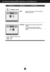
On Screen Display(OSD) Selection and Adjustment Main menu Sub menu Description WIDE Switch to full screen mode according to the upper menu , : Move EXIT : Exit 30 ORIGINAL Change the input image signal ratio to original. * This function works only if input resolution is lower than monitor ratio (16:9). : Move to input image signal.
On Screen Display(OSD) Selection and Adjustment Main menu Sub menu Description WIDE Switch to full screen mode according to the upper menu , : Move EXIT : Exit 30 ORIGINAL Change the input image signal ratio to original. * This function works only if input resolution is lower than monitor ratio (16:9). : Move to input image signal.
Owners Manual
Page 35
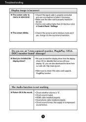
... • Set the color setting higher than 24 bits (true color) at Control Panel - Settings. Do you see an "Unrecognized monitor, Plug&Play (VESA DDC) monitor found" message? Troubleshooting Display image is incorrect G The screen color is mono or abnormal. • Check if the signal cable is... properly connected and use a screwdriver to install the display driver from our web site: http://www.lg.com. • Make sure ...
... • Set the color setting higher than 24 bits (true color) at Control Panel - Settings. Do you see an "Unrecognized monitor, Plug&Play (VESA DDC) monitor found" message? Troubleshooting Display image is incorrect G The screen color is mono or abnormal. • Check if the signal cable is... properly connected and use a screwdriver to install the display driver from our web site: http://www.lg.com. • Make sure ...


