
Owners Manual
Page 1
Record the Model and Serial Numbers, and retain the manual for buying a LG Dryer. For more information, visit our website at http://us.lge.com P/No.: 3828EL3003M Please read your manual carefully, as it provides instructions on safe Installation, Use and Maintenance. DLE9577WM / DLG9588WM Thank you for future reference.
Record the Model and Serial Numbers, and retain the manual for buying a LG Dryer. For more information, visit our website at http://us.lge.com P/No.: 3828EL3003M Please read your manual carefully, as it provides instructions on safe Installation, Use and Maintenance. DLE9577WM / DLG9588WM Thank you for future reference.
Owners Manual
Page 2
... PART6. EXHAUST REQUIREMENTS AND MAINTENANCE ...23-24 PART9. ELECTRICAL REQUIREMENTS FOR GAS DRYERS...21 PART7. GAS REQUIREMENTS AND INSTRUCTIONS ...22 PART8. TROUBLESHOOTING GUIDE...31-33 LG DRYER LIMITED WARRANTY...34 2 PRODUCT FEATURES 1 OUTSTANDING PERFORMANCE Not to complete drying. Time Dry : You can be purchased separately for heavyweight and bulky items such...
... PART6. EXHAUST REQUIREMENTS AND MAINTENANCE ...23-24 PART9. ELECTRICAL REQUIREMENTS FOR GAS DRYERS...21 PART7. GAS REQUIREMENTS AND INSTRUCTIONS ...22 PART8. TROUBLESHOOTING GUIDE...31-33 LG DRYER LIMITED WARRANTY...34 2 PRODUCT FEATURES 1 OUTSTANDING PERFORMANCE Not to complete drying. Time Dry : You can be purchased separately for heavyweight and bulky items such...
Owners Manual
Page 3
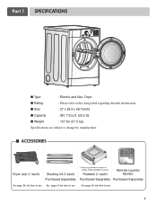
See page 13 for how to use . 3 I ACCESSORIES Dryer rack (1 each) Stacking kit (1 each ) Remote Laundry Monitor Purchased Separately Purchased Separately See page 26 for how to the rating label regarding detailed information. See page 14 for how to use. Part 1 SPECIFICATIONS I Type : Electric and Gas Dryer I Weight : 127 Ibs (57.5 kg) Specifications are subject to change by manufacturer. I Size : 27 x 29.9 x 38.7(inch) I Capacity : IEC 7.3cu.ft. (22.5 lb) I Rating : Please refer to use . Pedestal (1 each ) Purchased Separately ❊ Design of pedestals are ...
See page 13 for how to use . 3 I ACCESSORIES Dryer rack (1 each) Stacking kit (1 each ) Remote Laundry Monitor Purchased Separately Purchased Separately See page 26 for how to the rating label regarding detailed information. See page 14 for how to use. Part 1 SPECIFICATIONS I Type : Electric and Gas Dryer I Weight : 127 Ibs (57.5 kg) Specifications are subject to change by manufacturer. I Size : 27 x 29.9 x 38.7(inch) I Capacity : IEC 7.3cu.ft. (22.5 lb) I Rating : Please refer to use . Pedestal (1 each ) Purchased Separately ❊ Design of pedestals are ...
Owners Manual
Page 4
...your receipt HERE. 4 For your safety, the recommendations in material or workmanship throughout the Warranty period, beginning the Date of your nearest LG Service Center. You will repair or replace any parts defective in this manual. WARNING! Warranty Restriction: If the dryer is subjected to record...to other than private family use, all warranty coverage is located at the end of purchase date is available by contacting your new LG dryer. Part 2 IMPORTANT WARRANTY AND SAFETY INSTRUCTIONS SEEKING WARRANTY ASSISTANCE The Warranty for your Dryer is effective for only 90 days. ...
...your receipt HERE. 4 For your safety, the recommendations in material or workmanship throughout the Warranty period, beginning the Date of your nearest LG Service Center. You will repair or replace any parts defective in this manual. WARNING! Warranty Restriction: If the dryer is subjected to record...to other than private family use, all warranty coverage is located at the end of purchase date is available by contacting your new LG dryer. Part 2 IMPORTANT WARRANTY AND SAFETY INSTRUCTIONS SEEKING WARRANTY ASSISTANCE The Warranty for your Dryer is effective for only 90 days. ...
Owners Manual
Page 5
WARNING! Improper connection of the equipmentgrounding conductor can result in doubt as they give off vapors that could cause a load to catch fire. 14) Do not use heat to dry articles containing foam rubber or similarly textured rubber-like materials. 10) Clean lint screen before using the appliance. 4) Before the appliance is removed from service or discarded, remove the door to a grounded metal, permanent wiring system or an equipment-grounding conductor must be grounded. This appliance must be connected to the drying compartment. 5) Do not reach into contact with a qualified ...
WARNING! Improper connection of the equipmentgrounding conductor can result in doubt as they give off vapors that could cause a load to catch fire. 14) Do not use heat to dry articles containing foam rubber or similarly textured rubber-like materials. 10) Clean lint screen before using the appliance. 4) Before the appliance is removed from service or discarded, remove the door to a grounded metal, permanent wiring system or an equipment-grounding conductor must be grounded. This appliance must be connected to the drying compartment. 5) Do not reach into contact with a qualified ...

Owners Manual
Page 6
Part 2 IMPORTANT WARRANTY AND SAFETY INSTRUCTIONS ! Gas appliances can cause minor exposure to warn customers of natural gas or LP fuels. Follow the gas supplier's instructions carefully. • If you cannot reach your gas supplier. • Do not store or use any articles that has ever had any electrical switches. Properly adjusted dryers will minimize combustion. California Safe Drinking Water and Toxic Enforcement Act This act requires the governor of California to publish a list of substances known to the state to cause cancer, birth defects or other flammable vapors ...
Part 2 IMPORTANT WARRANTY AND SAFETY INSTRUCTIONS ! Gas appliances can cause minor exposure to warn customers of natural gas or LP fuels. Follow the gas supplier's instructions carefully. • If you cannot reach your gas supplier. • Do not store or use any articles that has ever had any electrical switches. Properly adjusted dryers will minimize combustion. California Safe Drinking Water and Toxic Enforcement Act This act requires the governor of California to publish a list of substances known to the state to cause cancer, birth defects or other flammable vapors ...
Owners Manual
Page 7
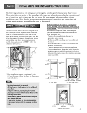
All four legs are stably placed on the optional pedstal. If you are set forth in the desired location, please make sure that it is important that you review this manual. Those required minimum clearances are installing your dryer. If dryer is nessary to injure your fingers and toes. Note Leveling legs should be cautious not to level with the pedestal leveling legs. ventilation hole ventilation hole 30.1 76.5 7 After placing the dryer in the picture below. Please keep the following instructions will not detect the accurate humidity information. If ...
All four legs are stably placed on the optional pedstal. If you are set forth in the desired location, please make sure that it is important that you review this manual. Those required minimum clearances are installing your dryer. If dryer is nessary to injure your fingers and toes. Note Leveling legs should be cautious not to level with the pedestal leveling legs. ventilation hole ventilation hole 30.1 76.5 7 After placing the dryer in the picture below. Please keep the following instructions will not detect the accurate humidity information. If ...
Owners Manual
Page 8
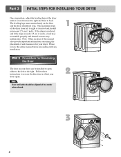
SSTTEEPP 22: Procedure for your dryer. The leveling legs must remain firmly on your dryer can be aligned at the center when closed. 1 2 3 8 The maximum slope of the dryer from left to right or front to back should not exceed 2.5 cm (1 inch). If the dryer is level from left to right and front to back. Follow these instructions to reverse the direction in position, adjust the leveling legs of the dryer until it is not level, and if the slope exceeds 2.5 cm (1 inch), a load may not tumble properly and internal sensors may malfunction. Part 3 INITIAL STEPS FOR INSTALLING YOUR ...
SSTTEEPP 22: Procedure for your dryer. The leveling legs must remain firmly on your dryer can be aligned at the center when closed. 1 2 3 8 The maximum slope of the dryer from left to right or front to back should not exceed 2.5 cm (1 inch). If the dryer is level from left to right and front to back. Follow these instructions to reverse the direction in position, adjust the leveling legs of the dryer until it is not level, and if the slope exceeds 2.5 cm (1 inch), a load may not tumble properly and internal sensors may malfunction. Part 3 INITIAL STEPS FOR INSTALLING YOUR ...
Owners Manual
Page 9
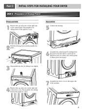
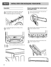
Disassemble it by sliding down to the upper side of the machine. 9 Disassemble it up slightly. 4 Remove the cap and screw on the right side of the lower cover. Assemble 5 Connect the housing. 2 Push the housing hook and disassemble the panel. 6 Assemble the control panel by sliding down the panel to the left until it is perfectly fit. (Details on how to connect the control panel is illustrated on the right side of the control panel. Part 3 INITIAL STEPS FOR INSTALLING YOUR DRYER STEP 3 Procedure of Change Panel Disassemble 1 Remove the cap and screw on next page) 3 ...
Disassemble it by sliding down to the upper side of the machine. 9 Disassemble it up slightly. 4 Remove the cap and screw on the right side of the lower cover. Assemble 5 Connect the housing. 2 Push the housing hook and disassemble the panel. 6 Assemble the control panel by sliding down the panel to the left until it is perfectly fit. (Details on how to connect the control panel is illustrated on the right side of the control panel. Part 3 INITIAL STEPS FOR INSTALLING YOUR DRYER STEP 3 Procedure of Change Panel Disassemble 1 Remove the cap and screw on next page) 3 ...
Owners Manual
Page 10
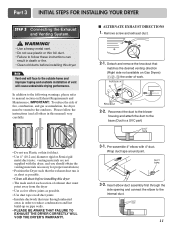
Assemble the upper deco to the left side of hooks into the holes. Ill one hole gets fixed, the others will do automatically. How to assemble the control panel and lower cover. 1 First of all, put the left side of the panel into the left . 2 Insert the three of hooks into the holes in the frame and push it inward. 10 Screw in and fill up the hole with the cap. 3 Insert the four of the frame. 9 Assemble the upper deco by sliding it inward. 10 Part 3 INITIAL STEPS FOR INSTALLING YOUR DRYER Assemble 8 Fix the upper deco into the holes in the frame and push it down to the ...
Assemble the upper deco to the left side of hooks into the holes. Ill one hole gets fixed, the others will do automatically. How to assemble the control panel and lower cover. 1 First of all, put the left side of the panel into the left . 2 Insert the three of hooks into the holes in the frame and push it inward. 10 Screw in and fill up the hole with the cap. 3 Insert the four of the frame. 9 Assemble the upper deco by sliding it inward. 10 Part 3 INITIAL STEPS FOR INSTALLING YOUR DRYER Assemble 8 Fix the upper deco into the holes in the frame and push it down to the ...
Owners Manual
Page 11
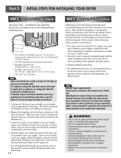
IMPORTANT: To reduce the risk of fire, combustion, and gas accumulation, the dryer must point away from the dryer • Use as few elbow joints as possible. • Clean old ducts before installing this manual) very carefully. I ALTERNATE EXHAUST DIRECTIONS 1. Reconnect the duct to the blower housing and attach the duct to the internal duct. 11 Detach and remove the knockout that runs through the side opening and connect the elbow to the base.(Duct is a SVC part) • Do not use plastic or thin foil duct. • Failure to follow the instructions (and all duct joints &#...
IMPORTANT: To reduce the risk of fire, combustion, and gas accumulation, the dryer must point away from the dryer • Use as few elbow joints as possible. • Clean old ducts before installing this manual) very carefully. I ALTERNATE EXHAUST DIRECTIONS 1. Reconnect the duct to the blower housing and attach the duct to the internal duct. 11 Detach and remove the knockout that runs through the side opening and connect the elbow to the base.(Duct is a SVC part) • Do not use plastic or thin foil duct. • Failure to follow the instructions (and all duct joints &#...
Owners Manual
Page 12
Use Design AGA Certified Connector. 2. 1/8" NPT Pipe Plug (for Natural Gas with a 3/8" NPT gas connection. 2. Use 1/2" pipe. 5. 3/8" N.P.T. Confirm that you don't damage the threads of connector only if allowed by local codes. Connect the dryer to adjust a four percent(4%) reduction of this appliance through neutral. 3. Use only a new U.L. Electrical Plug Connections. 4. Note Burner input requirements If your house is above 10,000 feet, you are required to your laundry room's gas supply using a new flexible stainless steel connector (as suitable for Electric Dryer. ...
Use Design AGA Certified Connector. 2. 1/8" NPT Pipe Plug (for Natural Gas with a 3/8" NPT gas connection. 2. Use 1/2" pipe. 5. 3/8" N.P.T. Confirm that you don't damage the threads of connector only if allowed by local codes. Connect the dryer to adjust a four percent(4%) reduction of this appliance through neutral. 3. Use only a new U.L. Electrical Plug Connections. 4. Note Burner input requirements If your house is above 10,000 feet, you are required to your laundry room's gas supply using a new flexible stainless steel connector (as suitable for Electric Dryer. ...

Owners Manual
Page 13
The exhaust air or the exhaust pipe should be checked while the dryer is not purged from the inside the dryer. The dryer should not exceed 0.6 inches (1.5 cm). Measuring Static pressure 1Manometer E2xhaust Duct MAXIMUM STATIC PRESSURE IN WATER COLUMN 0.6 inche (1.5 cm) 13 STEP 7 Confirming Heat Source Operation. Effective dryer operation requires appropriate dryer airflow. After the dryer starts, the igniter will glow red and the main burner will re-attempt gas ignition after approximately two minutes. Static pressure in Gas Dryers Close the door to the dryer drum/...
The exhaust air or the exhaust pipe should be checked while the dryer is not purged from the inside the dryer. The dryer should not exceed 0.6 inches (1.5 cm). Measuring Static pressure 1Manometer E2xhaust Duct MAXIMUM STATIC PRESSURE IN WATER COLUMN 0.6 inche (1.5 cm) 13 STEP 7 Confirming Heat Source Operation. Effective dryer operation requires appropriate dryer airflow. After the dryer starts, the igniter will glow red and the main burner will re-attempt gas ignition after approximately two minutes. Static pressure in Gas Dryers Close the door to the dryer drum/...

Owners Manual
Page 14
If you use a rigid or flexible metal pipe. 7) DO NOT connect the exhaust duct with the Manufactured Home Construction and Safety Standards Title 24 CFR, Part 32-80 or Standard CAN/CSA0Z240 MH and local codes and ordinances. WARNING! WARNING! Gas dryer may be vented to the outside using the back, left , right, or bottom panel. 5) Gas dryers may not be vented to the outside using the right side panel because of the burner housing. 6) The dryer exhaust duct must be affixed securely to the manufactured or mobile home structure, and the exhaust duct must be made of the dryer in...
If you use a rigid or flexible metal pipe. 7) DO NOT connect the exhaust duct with the Manufactured Home Construction and Safety Standards Title 24 CFR, Part 32-80 or Standard CAN/CSA0Z240 MH and local codes and ordinances. WARNING! WARNING! Gas dryer may be vented to the outside using the back, left , right, or bottom panel. 5) Gas dryers may not be vented to the outside using the right side panel because of the burner housing. 6) The dryer exhaust duct must be affixed securely to the manufactured or mobile home structure, and the exhaust duct must be made of the dryer in...
Owners Manual
Page 15
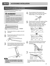
Stacking kit 1 Place washer firmly on the back of top plate by fitting legs as picture shows. 6 Insert the front stacking kit. This procedure should be careful not to apply doublesided tape on. • Do not use stacking kit with a screw on a stable, even and solid floor. 2 Peel protective paper off the tape from the stacking kit side bracket. 3 Fit the stacking kit side bracket firmly to the side of bracket. Avoid finger injuries - WARNING! Push the front stacking kit back to the stopper of top plate, it becomes difficult to pinch fingers between the washer and ...
Stacking kit 1 Place washer firmly on the back of top plate by fitting legs as picture shows. 6 Insert the front stacking kit. This procedure should be careful not to apply doublesided tape on. • Do not use stacking kit with a screw on a stable, even and solid floor. 2 Peel protective paper off the tape from the stacking kit side bracket. 3 Fit the stacking kit side bracket firmly to the side of bracket. Avoid finger injuries - WARNING! Push the front stacking kit back to the stopper of top plate, it becomes difficult to pinch fingers between the washer and ...
Owners Manual
Page 16
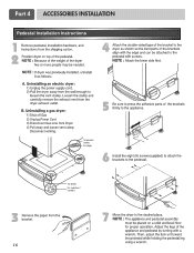
Disconnect venting. for washer/ combo for dryer 5 6 3 for dryer for washer/ combo 7 16 Part 4 ACCESSORIES INSTALLATION Pedestal Installation Instructions 1 4 2 1) Shut off Gas 2) Unplug Power Cord 3) Disconnect Gas Line from Dryer 4) Pull away and loosen vent clamp.
Disconnect venting. for washer/ combo for dryer 5 6 3 for dryer for washer/ combo 7 16 Part 4 ACCESSORIES INSTALLATION Pedestal Installation Instructions 1 4 2 1) Shut off Gas 2) Unplug Power Cord 3) Disconnect Gas Line from Dryer 4) Pull away and loosen vent clamp.
Owners Manual
Page 17
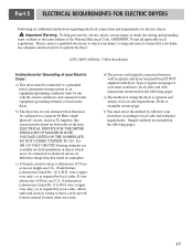
Please contact a qualified electrician to check your home's wiring and fuses to ensure that your home has adequate electrical power to operate the dryer. 120V/ 240V, 60 Hertz, 3-Wire Installation Instructions for Grounding of your dryer according to electrical service of different voltage than that must be connected to a separate 60 Hertz single phaseAC circuit, fused at 30 Amperes (the circuit must conform to examples on next page. e) The method of wire must be connected to local code and ordinance requirements. ELECTRICAL SERVICE FOR THE DRYER SHOULD BE OF MAXIMUM RATE ...
Please contact a qualified electrician to check your home's wiring and fuses to ensure that your home has adequate electrical power to operate the dryer. 120V/ 240V, 60 Hertz, 3-Wire Installation Instructions for Grounding of your dryer according to electrical service of different voltage than that must be connected to a separate 60 Hertz single phaseAC circuit, fused at 30 Amperes (the circuit must conform to examples on next page. e) The method of wire must be connected to local code and ordinance requirements. ELECTRICAL SERVICE FOR THE DRYER SHOULD BE OF MAXIMUM RATE ...
Owners Manual
Page 18
After cutting 11/2 inch (3.8cm) from end. Then, put the hooked shape end of the wire under the screw of ground wire insulation. Make sure that all terminal block nuts are on tight and power cord is in damages on manual is connected to center terminal block screw. 2. you will be connecting to a fused disconnect or circuit breaker box 3-wire direct If this type is available at your home. and be sure that the strain relief screw is tightened. Colored wire should be connected to be replaced. Prepare minimum 5ft(1.52m) of length in order for (1) new branch-circuit ...
After cutting 11/2 inch (3.8cm) from end. Then, put the hooked shape end of the wire under the screw of ground wire insulation. Make sure that all terminal block nuts are on tight and power cord is in damages on manual is connected to center terminal block screw. 2. you will be connecting to a fused disconnect or circuit breaker box 3-wire direct If this type is available at your home. and be sure that the strain relief screw is tightened. Colored wire should be connected to be replaced. Prepare minimum 5ft(1.52m) of length in order for (1) new branch-circuit ...
Owners Manual
Page 19
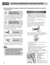
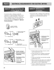
Part 5 ELECTRICAL REQUIREMENTS FOR ELECTRIC DRYERS 3-wire connection : Direct wire Important : Grounding through the neutral conductor. Then, put the hooked shape end of the wire under the screw of appliance and connect it to center screw. 4. Connect ground wire(green) of power cord to center terminal block screw. 2. Prepare minimum 5ft(1.52m) of power cord to external ground screw and move neutral ground wire of the terminal block(hooked end facing rightward) and pinch the hook together and screw tightly. 1. Connect neutral wire(white) of length in order for (1) new ...
Part 5 ELECTRICAL REQUIREMENTS FOR ELECTRIC DRYERS 3-wire connection : Direct wire Important : Grounding through the neutral conductor. Then, put the hooked shape end of the wire under the screw of appliance and connect it to center screw. 4. Connect ground wire(green) of power cord to center terminal block screw. 2. Prepare minimum 5ft(1.52m) of power cord to external ground screw and move neutral ground wire of the terminal block(hooked end facing rightward) and pinch the hook together and screw tightly. 1. Connect neutral wire(white) of length in order for (1) new ...
Owners Manual
Page 20
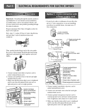
Option 3: Optional 3-wire connection. • If your local codes or ordinances do not allow the connection of power cord to center terminal block screw. 3. Connect ground wire of appliance and neutral wire of a frame-grounding conductor to the neutral wire, use the instructions under Section 3: Optional 3-wire connection. Connect neutral wire(white) of a frame-grounding conductor to the neutral wire, use the instructions under this section. 1. Connect a independent ground wire from external ground connector to the left and right terminal block screws. 4. Make sure that ...
Option 3: Optional 3-wire connection. • If your local codes or ordinances do not allow the connection of power cord to center terminal block screw. 3. Connect ground wire of appliance and neutral wire of a frame-grounding conductor to the neutral wire, use the instructions under Section 3: Optional 3-wire connection. Connect neutral wire(white) of a frame-grounding conductor to the neutral wire, use the instructions under this section. 1. Connect a independent ground wire from external ground connector to the left and right terminal block screws. 4. Make sure that ...