
Owner's Manual
Page 19
...within at 10 + 1.5 in . WARNING! • Use a new AGA or CSA approved gas supply line. • Install a shut-off valve, during any disassembly requires the attention and tools of the National Fuel Cas Code, ANSI Z223.1/NFPA 54. 1. Important Warning: The gas supply and service for lengths in...; • Use new flexible stainless steel connectors; • Use Teflon tape and pipe joint compound insoluble in . DO NOT attempt any disassembly of the dryer, any pressure testing of the gas supply system at test pressure equal to the type of gas is insoluble in order to...
...within at 10 + 1.5 in . WARNING! • Use a new AGA or CSA approved gas supply line. • Install a shut-off valve, during any disassembly requires the attention and tools of the National Fuel Cas Code, ANSI Z223.1/NFPA 54. 1. Important Warning: The gas supply and service for lengths in...; • Use new flexible stainless steel connectors; • Use Teflon tape and pipe joint compound insoluble in . DO NOT attempt any disassembly of the dryer, any pressure testing of the gas supply system at test pressure equal to the type of gas is insoluble in order to...
Service Manual
Page 4
WIRING DIAGRAM ...15 9. DIAGNOSTIC TEST ...16 9-1. TEST 3 MOTOR TEST 19 9-4. TEST 7 GAS VALVE TEST - DISASSEMBLY INSTRUCTIONS 26 12. CONTROL PANEL & PLATE ASSEMBLY 32 12-2. REPLACEMENT PARTS LIST 36 3 MOTOR DIAGRAM AND SCHEMATIC 13 7. CABINET & DOOR ASSEMBLY 33 12-3-1. SPECIFICATIONS ...4 2. CONTROL ...
WIRING DIAGRAM ...15 9. DIAGNOSTIC TEST ...16 9-1. TEST 3 MOTOR TEST 19 9-4. TEST 7 GAS VALVE TEST - DISASSEMBLY INSTRUCTIONS 26 12. CONTROL PANEL & PLATE ASSEMBLY 32 12-2. REPLACEMENT PARTS LIST 36 3 MOTOR DIAGRAM AND SCHEMATIC 13 7. CABINET & DOOR ASSEMBLY 33 12-3-1. SPECIFICATIONS ...4 2. CONTROL ...
Service Manual
Page 25
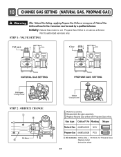
... to authorized servicers only. Propane Gas Orifice is set. STEP 1 : VALVE SETTING Full open "Change screw" STEP 2 : ORIFICE CHANGE Orifice Close "Change screw" Remove 2 screws. Disassemble the pipe assembly.
... to authorized servicers only. Propane Gas Orifice is set. STEP 1 : VALVE SETTING Full open "Change screw" STEP 2 : ORIFICE CHANGE Orifice Close "Change screw" Remove 2 screws. Disassemble the pipe assembly.
Service Manual
Page 27
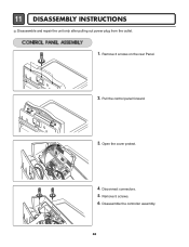
Disconnect connectors. 5. Disassemble the controller assembly. 26 Open the cover protect. 4. Remove 5 screws. 6. Remove 3 screws on the rear Panel. 2. Pull the control panel forward. 3. 11 DISASSEMBLY INSTRUCTIONS Disassemble and repair the unit only after pulling out power plug from the outlet. 1.
Disconnect connectors. 5. Disassemble the controller assembly. 26 Open the cover protect. 4. Remove 5 screws. 6. Remove 3 screws on the rear Panel. 2. Pull the control panel forward. 3. 11 DISASSEMBLY INSTRUCTIONS Disassemble and repair the unit only after pulling out power plug from the outlet. 1.
Service Manual
Page 29
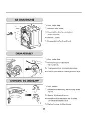
Open the top plate. 2. Disassemble the Tub Drum [Front]. -1 1. Open the top plate. -1 2. Slide the shield up and remove. 4. Disconnect the door lamp and electro sensor connector. 4. Remove the Cover ...
Open the top plate. 2. Disassemble the Tub Drum [Front]. -1 1. Open the top plate. -1 2. Slide the shield up and remove. 4. Disconnect the door lamp and electro sensor connector. 4. Remove the Cover ...


