
Service Manual
Page 3
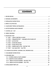
... 23 9-4. TEST 4 MOISTURE SENSOR 24 9-5. CONTROL PANEL & PLATE ASSEMBLY 37 12-2. DRUM & MOTOR ASSEMBLY : GAS TYPE 40 13. FEATURES AND BENEFITS ...6 3. WIRING DIAGRAM ...19 9. TEST 2 THERMISTOR TEST --- TEST 5 DOOR SWITCH TEST 25 9-6. DRUM & MOTOR ASSEMBLY : ELECTRIC TYPE 39 12-3-2. CONTROL LAY - TEST 1 120VAC ELECTRICAL SUPPLY 21 9-2. MEASURE WITH POWER OFF 22...
... 23 9-4. TEST 4 MOISTURE SENSOR 24 9-5. CONTROL PANEL & PLATE ASSEMBLY 37 12-2. DRUM & MOTOR ASSEMBLY : GAS TYPE 40 13. FEATURES AND BENEFITS ...6 3. WIRING DIAGRAM ...19 9. TEST 2 THERMISTOR TEST --- TEST 5 DOOR SWITCH TEST 25 9-6. DRUM & MOTOR ASSEMBLY : ELECTRIC TYPE 39 12-3-2. CONTROL LAY - TEST 1 120VAC ELECTRICAL SUPPLY 21 9-2. MEASURE WITH POWER OFF 22...

Service Manual
Page 15
... : 10Ω Resistance value : 20Ω Remark • Electric type Measure resistance of terminal to terminal Resistance value : 100~800Ω • Gas type 12. Thermistor 9. Frame Detect Measure resistance of terminal to terminal Temperature condition : 58°F ~ (10~40°C) 58°F ~ 104F (10~40°C) Resistance value : 10Ω...
... : 10Ω Resistance value : 20Ω Remark • Electric type Measure resistance of terminal to terminal Resistance value : 100~800Ω • Gas type 12. Thermistor 9. Frame Detect Measure resistance of terminal to terminal Temperature condition : 58°F ~ (10~40°C) 58°F ~ 104F (10~40°C) Resistance value : 10Ω...

Service Manual
Page 20
Unit must be used for Factory test /Service test. The display number is open Thermistor close See test 1 Display : See page See test 2 Once Motor Motor runs 70 ~ 239 Measured Moisture Value. Press "POWER" while pressing "MORE TIME", ... DIAGNOSTIC TEST MODE 1. Pressing the "START/PAUSE" button CHECKING ACTION DISPLAY CHECKING POINT REMARK None Electric control & Temperature sensor Won't power up Defective LED Thermistor open . Displays Moisture Sensor Operation: If moisture sensor is contacted with step 4 by pressing start 3 times) and step 4(by making sure the all ...
Unit must be used for Factory test /Service test. The display number is open Thermistor close See test 1 Display : See page See test 2 Once Motor Motor runs 70 ~ 239 Measured Moisture Value. Press "POWER" while pressing "MORE TIME", ... DIAGNOSTIC TEST MODE 1. Pressing the "START/PAUSE" button CHECKING ACTION DISPLAY CHECKING POINT REMARK None Electric control & Temperature sensor Won't power up Defective LED Thermistor open . Displays Moisture Sensor Operation: If moisture sensor is contacted with step 4 by pressing start 3 times) and step 4(by making sure the all ...

Service Manual
Page 22
Test 2 Thermistor Test --- Measurement Condition After turning Power off , or remains on. YES • Check if Control and 6Pin connector is significant. Air TEMP.[°F (°C)]... 80°F (27°C) 9.3 120°F (49°C) 4.3 160°F (71°C) 2.2 22 Difference between terminals after separating Harness NO From Thermistor assembly Connector. • Replace Thermistor. Resistance for Thermistor Temperature. Check if resistance is in the range of Table 1 when measuring resistance between actual and sensed temperature is properly connected. •...
Test 2 Thermistor Test --- Measurement Condition After turning Power off , or remains on. YES • Check if Control and 6Pin connector is significant. Air TEMP.[°F (°C)]... 80°F (27°C) 9.3 120°F (49°C) 4.3 160°F (71°C) 2.2 22 Difference between terminals after separating Harness NO From Thermistor assembly Connector. • Replace Thermistor. Resistance for Thermistor Temperature. Check if resistance is in the range of Table 1 when measuring resistance between actual and sensed temperature is properly connected. •...
Service Manual
Page 41
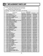
... 4561EL3002A K640 SWITCH,MICRO 3W40025D 3W40025D K620 CLAMP 4860EL3001A 4860EL3001A K510 BLOWER ASSEMBLY 5835EL1002A 5835EL1002A K520 HOUSING ASSEMBLY (MECH),BLOWER 3661EL1001C 3661EL1001C K550 THERMISTOR ASSEMBLY 6323EL2001B 6323EL2001B K560 THERMOSTAT ASSEMBLY 6931EL3002A 6931EL3002A K530 DUCT ASSEMBLY 5209EL1006A 5209EL1006A K400 TUB,DRUM[BACK] 3044EL0002B 3044EL0002B F200 DUCT ASSEMBLY 5209EL1001C... replacing any part of these components, read carefully the safety precautions in this manual. ¡Æ Note : S(Safety Parts), AL(Alternative parts) LG MODEL : TD-V10050E.
... 4561EL3002A K640 SWITCH,MICRO 3W40025D 3W40025D K620 CLAMP 4860EL3001A 4860EL3001A K510 BLOWER ASSEMBLY 5835EL1002A 5835EL1002A K520 HOUSING ASSEMBLY (MECH),BLOWER 3661EL1001C 3661EL1001C K550 THERMISTOR ASSEMBLY 6323EL2001B 6323EL2001B K560 THERMOSTAT ASSEMBLY 6931EL3002A 6931EL3002A K530 DUCT ASSEMBLY 5209EL1006A 5209EL1006A K400 TUB,DRUM[BACK] 3044EL0002B 3044EL0002B F200 DUCT ASSEMBLY 5209EL1001C... replacing any part of these components, read carefully the safety precautions in this manual. ¡Æ Note : S(Safety Parts), AL(Alternative parts) LG MODEL : TD-V10050E.
Service Manual
Page 42
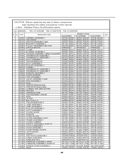
... read carefully the safety precautions in this manual. ¡Æ Note : S(Safety Parts), AL(Alternative parts) LG MODEL : TD-V10050E. TD-V10051E, TD-V10055E S AL LOC DESCRIPTION DLG5988W MODEL P/NO DLG5988B DLG3788W QTY A500 ...4860EL3001A 4860EL3001A 2 K510 BLOWER ASSEMBLY 5835EL1002A 5835EL1002A 5835EL1002A 1 K520 HOUSING ASSEMBLY (MECH),BLOWER 3661EL1001C 3661EL1001C 3661EL1001C 1 K550 THERMISTOR ASSEMBLY 6323EL2001B 6323EL2001B 6323EL2001B 1 K560 THERMOSTAT ASSEMBLY 6931EL3002A 6931EL3002A 6931EL3002A 1 K530 DUCT ASSEMBLY 5209EL1006A 5209EL1006A 5209EL1006A 1 K400 ...
... read carefully the safety precautions in this manual. ¡Æ Note : S(Safety Parts), AL(Alternative parts) LG MODEL : TD-V10050E. TD-V10051E, TD-V10055E S AL LOC DESCRIPTION DLG5988W MODEL P/NO DLG5988B DLG3788W QTY A500 ...4860EL3001A 4860EL3001A 2 K510 BLOWER ASSEMBLY 5835EL1002A 5835EL1002A 5835EL1002A 1 K520 HOUSING ASSEMBLY (MECH),BLOWER 3661EL1001C 3661EL1001C 3661EL1001C 1 K550 THERMISTOR ASSEMBLY 6323EL2001B 6323EL2001B 6323EL2001B 1 K560 THERMOSTAT ASSEMBLY 6931EL3002A 6931EL3002A 6931EL3002A 1 K530 DUCT ASSEMBLY 5209EL1006A 5209EL1006A 5209EL1006A 1 K400 ...
