
Service Manual
Page 3
DRYER CYCLE PROCESS ...13 5. MOTOR DIAGRAM AND SCHEMATIC 17 7. WIRING DIAGRAM ...19 9. CONTROL PANEL & PLATE ASSEMBLY 37 12-2. DIAGNOSTIC TEST ...20 9-1. EXPLODED VIEW ...37 12-1. CABINET & DOOR ... TESTING INFORMATION 14 6. TEST 6 HEATER SWITCH TEST - GAS TYPE 27 10. SPECIFICATIONS ...4 2. DISASSEMBLY INSTRUCTIONS 30 12. DRUM & MOTOR ASSEMBLY : GAS TYPE 40 13. OUT ...18 8. MEASURE WITH POWER OFF 22 9-3. CONTENTS 1. DRUM & MOTOR ASSEMBLY : ELECTRIC TYPE 39 12-3-2. TEST 7 GAS VALVE TEST - ELECTRIC TYPE 26 9-7. TEST 5 DOOR SWITCH TEST 25 9-6. CONTROL...
DRYER CYCLE PROCESS ...13 5. MOTOR DIAGRAM AND SCHEMATIC 17 7. WIRING DIAGRAM ...19 9. CONTROL PANEL & PLATE ASSEMBLY 37 12-2. DIAGNOSTIC TEST ...20 9-1. EXPLODED VIEW ...37 12-1. CABINET & DOOR ... TESTING INFORMATION 14 6. TEST 6 HEATER SWITCH TEST - GAS TYPE 27 10. SPECIFICATIONS ...4 2. DISASSEMBLY INSTRUCTIONS 30 12. DRUM & MOTOR ASSEMBLY : GAS TYPE 40 13. OUT ...18 8. MEASURE WITH POWER OFF 22 9-3. CONTENTS 1. DRUM & MOTOR ASSEMBLY : ELECTRIC TYPE 39 12-3-2. TEST 7 GAS VALVE TEST - ELECTRIC TYPE 26 9-7. TEST 5 DOOR SWITCH TEST 25 9-6. CONTROL...

Service Manual
Page 5
... Color Top Plate Door Trim Blue White Black Porcelain Chromate + STS Deco Blue White Painted Blue White POWER SUPPLY 120V / 240V 60Hz (26A) ELECTRICITY CONSUMPTION MOTOR HEATER LAMP 250W (4.5A) 5400W (22.5A) 15 W (125mA) AC 120V AC 240V (ELECTRIC TYPE) AC 120V GAS VALVE CONTROL TYPE 13 W (110mA) x 2 Electronic AC...
... Color Top Plate Door Trim Blue White Black Porcelain Chromate + STS Deco Blue White Painted Blue White POWER SUPPLY 120V / 240V 60Hz (26A) ELECTRICITY CONSUMPTION MOTOR HEATER LAMP 250W (4.5A) 5400W (22.5A) 15 W (125mA) AC 120V AC 240V (ELECTRIC TYPE) AC 120V GAS VALVE CONTROL TYPE 13 W (110mA) x 2 Electronic AC...

Service Manual
Page 13
...±5°C) Manual FRESHEN UP Dry ** (MID HIGH) - 20min Saturation (66±5°C) (5min) (47±5°C) 3Hr AIR DRY - - 30min Saturation No heater N/A N/A Load Motor Heater Off Time: 6min On Time: 10sec Temperature Control for each cycle * Sensor dry : "Dry Level" is set by users. ** Manual dry : "Temperature control" is...
...±5°C) Manual FRESHEN UP Dry ** (MID HIGH) - 20min Saturation (66±5°C) (5min) (47±5°C) 3Hr AIR DRY - - 30min Saturation No heater N/A N/A Load Motor Heater Off Time: 6min On Time: 10sec Temperature Control for each cycle * Sensor dry : "Dry Level" is set by users. ** Manual dry : "Temperature control" is...

Service Manual
Page 15
... : > 1.5kg ~ Resistance value : > 1.5~2.5kg 11. Heater 8. Component 7. Frame Detect Measure resistance of terminal to terminal Resistance value : 100~800Ω • Gas type 12. Thermistor 9. Motor Test Procedure Measure resistance of terminal to terminal Open at 370°F ((Maximum) Close at 320°F Resistance value ∞ Resistance value < 1Ω • Gas...
... : > 1.5kg ~ Resistance value : > 1.5~2.5kg 11. Heater 8. Component 7. Frame Detect Measure resistance of terminal to terminal Resistance value : 100~800Ω • Gas type 12. Thermistor 9. Motor Test Procedure Measure resistance of terminal to terminal Open at 370°F ((Maximum) Close at 320°F Resistance value ∞ Resistance value < 1Ω • Gas...

Service Manual
Page 17
6 MOTOR DIAGRAM AND SCHEMATIC NOTE When checking Component, be sure to turn Power off, then do voltage discharge sufficiently. Contact On / Off by Centrifugal Switch STOP MODE (When Motor does not operate) RUN MODE (Motor operates) Centrifugal switch Centrifugal switch (Pull Drive forward) 17
6 MOTOR DIAGRAM AND SCHEMATIC NOTE When checking Component, be sure to turn Power off, then do voltage discharge sufficiently. Contact On / Off by Centrifugal Switch STOP MODE (When Motor does not operate) RUN MODE (Motor operates) Centrifugal switch Centrifugal switch (Pull Drive forward) 17

Service Manual
Page 20
... used for Factory test /Service test. Press "POWER" while pressing "MORE TIME", and "LESS TIME" simultaneously. Buzzer beeps seven times During check, Motor on & Heater If the door is open ) ACTIVATING THE DIAGNOSTIC TEST MODE 1. Do not use this DIAGNOSTIC TEST other than specified. 2. Off +...ELECTRIC TYPE : Heater runs GAS TYPE : GAS Valve runs (Display the Temperature of Inside drum.) Gas valve See test 7 4 times Control Off During check, Motor & Heater Off + Lamp On + If the door is closed. Proceed again from the step 1 all the electric devices shut off ) 2. Pressing the "...
... used for Factory test /Service test. Press "POWER" while pressing "MORE TIME", and "LESS TIME" simultaneously. Buzzer beeps seven times During check, Motor on & Heater If the door is open ) ACTIVATING THE DIAGNOSTIC TEST MODE 1. Do not use this DIAGNOSTIC TEST other than specified. 2. Off +...ELECTRIC TYPE : Heater runs GAS TYPE : GAS Valve runs (Display the Temperature of Inside drum.) Gas valve See test 7 4 times Control Off During check, Motor & Heater Off + Lamp On + If the door is closed. Proceed again from the step 1 all the electric devices shut off ) 2. Pressing the "...

Service Manual
Page 23
... • Drum Belt takes off , and do voltage discharge. (When discharging, contact the metal plug of Outlet Thermostat attached to Motor Bracket operate Level by drum belt? Measurement Condition Turn the Dryer's Power Off, then measure resistance. " (Brown wire)? YES Measure... 3Ω between Idler Switch terminals? No fan will work. Test 3 Motor test Caution Before measuring resistance, be sure to turn Power off from • Motor Pulley. • Replace Idler Switch. • Check Motor.(Refer to 'Motor Diagram & Check') • Check if Control Connector is closed . "...
... • Drum Belt takes off , and do voltage discharge. (When discharging, contact the metal plug of Outlet Thermostat attached to Motor Bracket operate Level by drum belt? Measurement Condition Turn the Dryer's Power Off, then measure resistance. " (Brown wire)? YES Measure... 3Ω between Idler Switch terminals? No fan will work. Test 3 Motor test Caution Before measuring resistance, be sure to turn Power off from • Motor Pulley. • Replace Idler Switch. • Check Motor.(Refer to 'Motor Diagram & Check') • Check if Control Connector is closed . "...

Service Manual
Page 25
...NO Measure while Door is open . YES • Door switch Check (Refer to Component testing.) • Check Lamp. (When opening Door, Drum motor and Trouble Symptom Heater run continuously; NO • Door switch Check (Refer to Component testing.) Measure while Door is closed . YES • ... WH3, RD3 after NO taking WH3, RD3 out from Controller. " (White wire) and "RD3- Check if resistance is not sensed. (Drum motor will flash at 0.5 second intervals.) Measurement Condition After turning Dryer Power Off, measure resistance. Check Harness-linking connector. 25
...NO Measure while Door is open . YES • Door switch Check (Refer to Component testing.) • Check Lamp. (When opening Door, Drum motor and Trouble Symptom Heater run continuously; NO • Door switch Check (Refer to Component testing.) Measure while Door is closed . YES • ... WH3, RD3 after NO taking WH3, RD3 out from Controller. " (White wire) and "RD3- Check if resistance is not sensed. (Drum motor will flash at 0.5 second intervals.) Measurement Condition After turning Dryer Power Off, measure resistance. Check Harness-linking connector. 25
Service Manual
Page 26
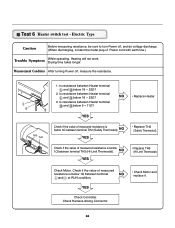
... Type Caution Before measuring resistance, be sure to turn Power off , measure the resistance. Is resistance between terminal NO and at RUN condition. • Check Motor and replace it. NO YES • Replace TH2 (Safety Thermostat). Is resistance between Heater terminal and below 1Ω between Heater terminal and below 18 ~ 22...
... Type Caution Before measuring resistance, be sure to turn Power off , measure the resistance. Is resistance between terminal NO and at RUN condition. • Check Motor and replace it. NO YES • Replace TH2 (Safety Thermostat). Is resistance between Heater terminal and below 1Ω between Heater terminal and below 18 ~ 22...

Service Manual
Page 33
... lamp shield in place. 3. Remove 4 screws. 5. Remove the Cabinet Cover and Tub drum [front]. -2 3. Disconnect the door lamp and electrode sensor connector. 4. Loosen belt from motor and idler pulleys. 4. 1. Disassemble the Tub Drum [Front]. -1 1. Remove the bulb and replace with a 15 watt, 120 volt candelabra-base bulb. 5. Disassemble the top plate...
... lamp shield in place. 3. Remove 4 screws. 5. Remove the Cabinet Cover and Tub drum [front]. -2 3. Disconnect the door lamp and electrode sensor connector. 4. Loosen belt from motor and idler pulleys. 4. 1. Disassemble the Tub Drum [Front]. -1 1. Remove the bulb and replace with a 15 watt, 120 volt candelabra-base bulb. 5. Disassemble the top plate...

Service Manual
Page 35
Remove the Drum assembly. 4. Remove the fan. 7. Disconnect electrode sensor. 1. Remove 2 screws and cover(Air guide). 5. Disassemble the top plate. 2. 1. Remove Cover Gride. 4. Remove the Cabinet Cover and Tub Drum [Front]. 3. Disconnect the motor clamp and motor. 1. Disassembly the top plate. 2. Remove 7 screws. 5. Remove the Tub Drum [Rear] towards the front. 35 Remove the bolt and washer. 6. Remove the Cabinet Cover and Tub Drum [Front]. 3. Remove the Drum assembly. 4. Remove the filter. 2. Remove 3 screws. 3.
Remove the Drum assembly. 4. Remove the fan. 7. Disconnect electrode sensor. 1. Remove 2 screws and cover(Air guide). 5. Disassemble the top plate. 2. 1. Remove Cover Gride. 4. Remove the Cabinet Cover and Tub Drum [Front]. 3. Disconnect the motor clamp and motor. 1. Disassembly the top plate. 2. Remove 7 screws. 5. Remove the Tub Drum [Rear] towards the front. 35 Remove the bolt and washer. 6. Remove the Cabinet Cover and Tub Drum [Front]. 3. Remove the Drum assembly. 4. Remove the filter. 2. Remove 3 screws. 3.

Service Manual
Page 39
Drum & Motor Assembly : Electric Type F200 K400 K120 K140 K100 K130 K250 K310 K330 K320 K340 K222 K221 K620 K210 K250 K550 K560 K610 K240 F130 F110 F120 K530 F140 K640 K600 K510 K520 K650 39 12-3-1.
Drum & Motor Assembly : Electric Type F200 K400 K120 K140 K100 K130 K250 K310 K330 K320 K340 K222 K221 K620 K210 K250 K550 K560 K610 K240 F130 F110 F120 K530 F140 K640 K600 K510 K520 K650 39 12-3-1.
Service Manual
Page 41
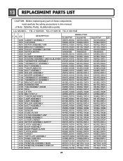
...these components, read carefully the safety precautions in this manual. ¡Æ Note : S(Safety Parts), AL(Alternative parts) LG MODEL : TD-V10050E. TD-V10051E, TD-V10055E S AL LOC DESCRIPTION MODEL P/NO DLE5977W DLE5977B A500 CABINET ASSEMBLY 3091EL0003A ...3091EL0003C A510 CAP,DRIER 5006EL3001D 5006EL3001E K610 MOTOR ASSEMBLY,WM 4681EL1002A 4681EL1002A K600 BRACKET ASSEMBLY 4811EL1002A 4811EL1002A K650 PULLEY ASSEMBLY,MOTOR 4561EL3002A 4561EL3002A K640 SWITCH,MICRO 3W40025D 3W40025D K620 CLAMP 4860EL3001A 4860EL3001A K510 ...
...these components, read carefully the safety precautions in this manual. ¡Æ Note : S(Safety Parts), AL(Alternative parts) LG MODEL : TD-V10050E. TD-V10051E, TD-V10055E S AL LOC DESCRIPTION MODEL P/NO DLE5977W DLE5977B A500 CABINET ASSEMBLY 3091EL0003A ...3091EL0003C A510 CAP,DRIER 5006EL3001D 5006EL3001E K610 MOTOR ASSEMBLY,WM 4681EL1002A 4681EL1002A K600 BRACKET ASSEMBLY 4811EL1002A 4811EL1002A K650 PULLEY ASSEMBLY,MOTOR 4561EL3002A 4561EL3002A K640 SWITCH,MICRO 3W40025D 3W40025D K620 CLAMP 4860EL3001A 4860EL3001A K510 ...
Service Manual
Page 42
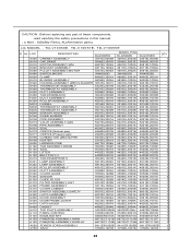
...components, read carefully the safety precautions in this manual. ¡Æ Note : S(Safety Parts), AL(Alternative parts) LG MODEL : TD-V10050E. TD-V10051E, TD-V10055E S AL LOC DESCRIPTION DLG5988W MODEL P/NO DLG5988B DLG3788W QTY A500 ... 3091EL0003B 3091EL0003D 3091EL0003B 1 A510 CAP,DRIER 5006EL3001D 5006EL3001E 5006EL3001D 2 K610 MOTOR ASSEMBLY,WM 4681EL1002A 4681EL1002A 4681EL1002A 1 K600 BRACKET ASSEMBLY 4811EL1002A 4811EL1002A 4811EL1002A 1 K650 PULLEY ASSEMBLY,MOTOR 4561EL3002A 4561EL3002A 4561EL3002A 1 K640 SWITCH,MICRO 3W40025D 3W40025D 3W40025D 1 K620 ...
...components, read carefully the safety precautions in this manual. ¡Æ Note : S(Safety Parts), AL(Alternative parts) LG MODEL : TD-V10050E. TD-V10051E, TD-V10055E S AL LOC DESCRIPTION DLG5988W MODEL P/NO DLG5988B DLG3788W QTY A500 ... 3091EL0003B 3091EL0003D 3091EL0003B 1 A510 CAP,DRIER 5006EL3001D 5006EL3001E 5006EL3001D 2 K610 MOTOR ASSEMBLY,WM 4681EL1002A 4681EL1002A 4681EL1002A 1 K600 BRACKET ASSEMBLY 4811EL1002A 4811EL1002A 4811EL1002A 1 K650 PULLEY ASSEMBLY,MOTOR 4561EL3002A 4561EL3002A 4561EL3002A 1 K640 SWITCH,MICRO 3W40025D 3W40025D 3W40025D 1 K620 ...

