
Service Manual
Page 1
Website:http://www.LGservice.com [For U.S.A] www.lg.ca [For Canada] ELECTRIC & GAS DRYER SERVICE MANUAL CAUTION READ THIS MANUAL CAREFULLY TO DIAGNOSE TROUBLES CORRECTLY BEFORE OFFERING SERVICE. MODEL : DLE5911W DLE2511W DLE5932W DLE5932S DLE2532W DLE0332W DLG5911W DLG2511W DLG5932W DLG5932S DLG2532W DLG0332W
Website:http://www.LGservice.com [For U.S.A] www.lg.ca [For Canada] ELECTRIC & GAS DRYER SERVICE MANUAL CAUTION READ THIS MANUAL CAREFULLY TO DIAGNOSE TROUBLES CORRECTLY BEFORE OFFERING SERVICE. MODEL : DLE5911W DLE2511W DLE5932W DLE5932S DLE2532W DLE0332W DLG5911W DLG2511W DLG5932W DLG5932S DLG2532W DLG0332W
Service Manual
Page 4
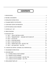
... 23 10. DRUM & MOTOR ASSEMBLY : GAS TYPE 35 13. TEST 7 GAS VALVE TEST - FEATURES AND BENEFITS ...5 3. INSTALLATION INSTRUCTIONS 6 4. CONTROL LAY - DIAGNOSTIC TEST ...16 9-1. SPECIFICATIONS ...4 2. COLUMBUS DRYER CYCLE PROCESS 9 5. EXPLODED VIEW ...32 12-1. DRUM & MOTOR ASSEMBLY : ELECTRIC TYPE 34 12-3-2. TEST 2 THERMISTOR TEST --- TEST 3 MOTOR TEST 19 9-4. OUT ...14 8. TEST 6 HEATER SWITCH...
... 23 10. DRUM & MOTOR ASSEMBLY : GAS TYPE 35 13. TEST 7 GAS VALVE TEST - FEATURES AND BENEFITS ...5 3. INSTALLATION INSTRUCTIONS 6 4. CONTROL LAY - DIAGNOSTIC TEST ...16 9-1. SPECIFICATIONS ...4 2. COLUMBUS DRYER CYCLE PROCESS 9 5. EXPLODED VIEW ...32 12-1. DRUM & MOTOR ASSEMBLY : ELECTRIC TYPE 34 12-3-2. TEST 2 THERMISTOR TEST --- TEST 3 MOTOR TEST 19 9-4. OUT ...14 8. TEST 6 HEATER SWITCH...
Service Manual
Page 5
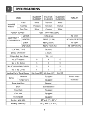
...Temperature Controls 5 5 5 No. Weight (lbs): Net / Gross 126 / 144 No. 1 SPECIFICATIONS ITEM DLE5932W DLE5932S DLE2532W DLG5932W DLG5932S DLG2532W REMARK Material & Finishes Color Top Plate Door Trim White Porcelain Silver Titanium Porcelain Chrome White ...Beeper High / Low / Off High / Low / Off On / Off Sensor Moisture Temperature Equipped Equipped Electro sensor Thermistor Reversible Door Adopted Drum Stainless Steel Dryer Rack Equipped Child lock Equipped Interior Light Equipped Product (WXHXD) Packing (WXHXD) 27" x 42 3/4" x 28 1/3" 29 1/2" x 44 3/4" x ...
...Temperature Controls 5 5 5 No. Weight (lbs): Net / Gross 126 / 144 No. 1 SPECIFICATIONS ITEM DLE5932W DLE5932S DLE2532W DLG5932W DLG5932S DLG2532W REMARK Material & Finishes Color Top Plate Door Trim White Porcelain Silver Titanium Porcelain Chrome White ...Beeper High / Low / Off High / Low / Off On / Off Sensor Moisture Temperature Equipped Equipped Electro sensor Thermistor Reversible Door Adopted Drum Stainless Steel Dryer Rack Equipped Child lock Equipped Interior Light Equipped Product (WXHXD) Packing (WXHXD) 27" x 42 3/4" x 28 1/3" 29 1/2" x 44 3/4" x ...
Service Manual
Page 7
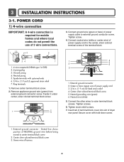
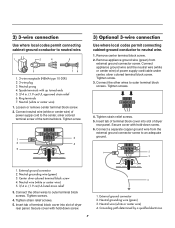
... it under center, silver colored terminal block screw. 1 2 3 1 4 5 2 6 3 1. External ground connector - Green wire of power supply cable to the center, silver colored terminal screw of dryer rear panel Secure cover with upturned ends 6. 3/4 in . (1.9 cm) UL-listed strain relief 4. 3 INSTALLATION INSTRUCTIONS 3-1. Connect ground wire (green or bare) of harness 6 Remove appliance...
... it under center, silver colored terminal block screw. 1 2 3 1 4 5 2 6 3 1. External ground connector - Green wire of power supply cable to the center, silver colored terminal screw of dryer rear panel Secure cover with upturned ends 6. 3/4 in . (1.9 cm) UL-listed strain relief 4. 3 INSTALLATION INSTRUCTIONS 3-1. Connect ground wire (green or bare) of harness 6 Remove appliance...
Service Manual
Page 8
... with hold -down screw. 7 4 1. Ring terminals 7. Connect appliance ground wire and the neutral wire (white or center wire) of dryer rear panel. Connect the other wires to outer terminal block screws. Neutral grounding wire (green) 3. Secure cover with hold -down screw. ...wire (white or center wire) 5. 3/4 in . (1.9 cm) UL approved strain relief 6. Connect neutral wire (white or center wire) of dryer rear panel. Remove center terminal block screw. 2. Connect the other wires to outer terminal block screws. Tighten strain relief screws. 5. Grounding path ...
... with hold -down screw. 7 4 1. Ring terminals 7. Connect appliance ground wire and the neutral wire (white or center wire) of dryer rear panel. Connect the other wires to outer terminal block screws. Neutral grounding wire (green) 3. Secure cover with hold -down screw. ...wire (white or center wire) 5. 3/4 in . (1.9 cm) UL approved strain relief 6. Connect neutral wire (white or center wire) of dryer rear panel. Remove center terminal block screw. 2. Connect the other wires to outer terminal block screws. Tighten strain relief screws. 5. Grounding path ...
Service Manual
Page 9
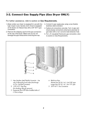
... 20' (6.1 m) - Make sure you do not damage the pipe thread when removing the cap. 3. Dryer is equipped for gas leaks with the type of gas in your dryer is equipped at the rear of dryer 4 Black Iron Pipe Shorter than 20' (6.1 m) - Tighten all pipe connections (internal & external) for...shipping cap from the gas connection at the factory for checking inlet gas pressure) 3 Equipment Shut-Off Valve-Installed within 6' (1.8 m) of the dryer. Use 1/2" pipe 5 3/8" N.P.T. Use only if allowed by local codes (Use Design A.G.A. Make certain your laundry room. Gas Connection 8
... 20' (6.1 m) - Make sure you do not damage the pipe thread when removing the cap. 3. Dryer is equipped for gas leaks with the type of gas in your dryer is equipped at the rear of dryer 4 Black Iron Pipe Shorter than 20' (6.1 m) - Tighten all pipe connections (internal & external) for...shipping cap from the gas connection at the factory for checking inlet gas pressure) 3 Equipment Shut-Off Valve-Installed within 6' (1.8 m) of the dryer. Use 1/2" pipe 5 3/8" N.P.T. Use only if allowed by local codes (Use Design A.G.A. Make certain your laundry room. Gas Connection 8

Service Manual
Page 10
... cycle * Sense dry : "Dry Level" is set by users. ** Manual dry : "Temperature control" is set by users. 9 Default settings can be adjusted by users. 4 COLUMBUS DRYER CYCLE PROCESS Cycle Default Conditions of operation and termination Drying Cooling Wrinkle care Temp-
... cycle * Sense dry : "Dry Level" is set by users. ** Manual dry : "Temperature control" is set by users. 9 Default settings can be adjusted by users. 4 COLUMBUS DRYER CYCLE PROCESS Cycle Default Conditions of operation and termination Drying Cooling Wrinkle care Temp-
Service Manual
Page 16
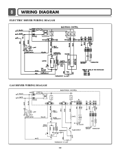
8 WIRING DIAGRAM ELECTRIC DRYER WIRING DIAGAM GAS DRYER WIRING DIAGAM 15
8 WIRING DIAGRAM ELECTRIC DRYER WIRING DIAGAM GAS DRYER WIRING DIAGAM 15
Service Manual
Page 18
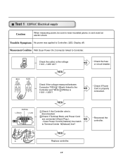
...- N(White) L (Black) L (Led) YES Check if the Controller wire is the voltage 110V ~ 125V AC? " (Black) linked to Controller. (LED, Display off) Measurement Condition With Dryer Power On; Test 1 120VAC Electrical supply Caution When measuring power, be sure to wear insulated gloves, to Controller. YES NO • Check the fuse or...
...- N(White) L (Black) L (Led) YES Check if the Controller wire is the voltage 110V ~ 125V AC? " (Black) linked to Controller. (LED, Display off) Measurement Condition With Dryer Power On; Test 1 120VAC Electrical supply Caution When measuring power, be sure to wear insulated gloves, to Controller. YES NO • Check the fuse or...
Service Manual
Page 20
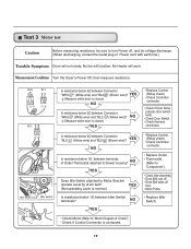
... switch knob. • Check Door Switch. • Check Harness connection. YES NO Is resistance below 1Ω between Connector "WH3- " (Yellow wire)? Measurement Condition Turn the Dryer's Power Off, then measure resistance. NO YES Does Idle Switch attached to blower housing? " (Brown wire)? Test 3 Motor test Caution Before measuring resistance, be sure...
... switch knob. • Check Door Switch. • Check Harness connection. YES NO Is resistance below 1Ω between Connector "WH3- " (Yellow wire)? Measurement Condition Turn the Dryer's Power Off, then measure resistance. NO YES Does Idle Switch attached to blower housing? " (Brown wire)? Test 3 Motor test Caution Before measuring resistance, be sure...

Service Manual
Page 21
... discharge. (When discharging, contact the metal plug of Power cord with earth line.) Trouble Symptom Degree of Table 2 during Diagnostic Test? 2. Measurement Condition Turn the Dryer's Power Off, then measure resistance. NO YES • Check Electro Load and • Harness Connector. • Check Harness- Is the measurement within the range of...
... discharge. (When discharging, contact the metal plug of Power cord with earth line.) Trouble Symptom Degree of Table 2 during Diagnostic Test? 2. Measurement Condition Turn the Dryer's Power Off, then measure resistance. NO YES • Check Electro Load and • Harness Connector. • Check Harness- Is the measurement within the range of...
Service Manual
Page 22
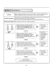
... Controller. Door Close is below 1Ω between "BL2- Check if resistance is not sensed. (Drum motor will flash at 0.5 second intervals.) Measurement Condition After turning Dryer Power Off, measure resistance. " (White wire) after NO taking Connector WH3, BL2 out from Controller. " (White wire) after YES taking Connector WH3, BL2 out from...
... Controller. Door Close is below 1Ω between "BL2- Check if resistance is not sensed. (Drum motor will flash at 0.5 second intervals.) Measurement Condition After turning Dryer Power Off, measure resistance. " (White wire) after NO taking Connector WH3, BL2 out from Controller. " (White wire) after YES taking Connector WH3, BL2 out from...
Service Manual
Page 24
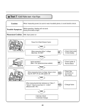
...? (after 1 min, Igniter becomes reddish) YES NO • Check Igniter & Frame detect When measuring Valve 2 voltage, Value is more than AC 90V? Measurement Condition With dryer power on "Valve 1", "Valve 2", Value is more than1.5 ~ 2.5kΩ? (Measure after Igniter off) YES NO • Check Gas connection or Gas supply When measuring...
...? (after 1 min, Igniter becomes reddish) YES NO • Check Igniter & Frame detect When measuring Valve 2 voltage, Value is more than AC 90V? Measurement Condition With dryer power on "Valve 1", "Valve 2", Value is more than1.5 ~ 2.5kΩ? (Measure after Igniter off) YES NO • Check Gas connection or Gas supply When measuring...
Service Manual
Page 29
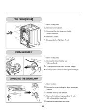
... Tub drum [front]. -2 3. Open the door. 2. Disconnect the door lamp and electro sensor connector. 4. Open the top plate. -1 2. Carefully remove Drum out through front of dryer. 1. Remove 4 screws. 5. Slide the shield up and remove. 4. Remove the screw holding the drum lamp shield in place. 3. Remove the bulb and replace with a 15...
... Tub drum [front]. -2 3. Open the door. 2. Disconnect the door lamp and electro sensor connector. 4. Open the top plate. -1 2. Carefully remove Drum out through front of dryer. 1. Remove 4 screws. 5. Slide the shield up and remove. 4. Remove the screw holding the drum lamp shield in place. 3. Remove the bulb and replace with a 15...
Service Manual
Page 30
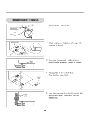
Detach and remove the bottom, left or right side knockout as desired. DUCT TAPE 3. DUCT TAPE 5. DUCT TAPE 4. Wrap duct tape around joint. Remove screw & exhaust duct. Reconnect the new duct[11 in(28cm)] to the blower housing, and attach the duct to the dryer internal duct. 29 Insert duct assembly, elbow first, through the side opening and connect the elbow to the base. 1. PORTION "A" 2. Pre-assemble 4" elbow with 4" duct.
Detach and remove the bottom, left or right side knockout as desired. DUCT TAPE 3. DUCT TAPE 5. DUCT TAPE 4. Wrap duct tape around joint. Remove screw & exhaust duct. Reconnect the new duct[11 in(28cm)] to the blower housing, and attach the duct to the dryer internal duct. 29 Insert duct assembly, elbow first, through the side opening and connect the elbow to the base. 1. PORTION "A" 2. Pre-assemble 4" elbow with 4" duct.


