Service Manual
Page 15
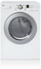
...Ω • Heater case Hi limit • Electric type • Blow housing Safety • Electric type 5. 5 COMPONENT TESTING INFORMATION ! Outlet Thermostat ( Auto reset) • Check Top Marking: N85 4. Hi limit Thermostat (Auto reset) 3. Lamp holder Test Procedure Check result Remark Measure resistance of terminal Resistance value: to Open condition. Idler switch Measure... resistance of terminal to terminal Open at 185 ± 9°F (85 ± 5°C) Close at 149 ± 9°F (65 ± 5°C) Same shape as Outlet Thermostat.
...Ω • Heater case Hi limit • Electric type • Blow housing Safety • Electric type 5. 5 COMPONENT TESTING INFORMATION ! Outlet Thermostat ( Auto reset) • Check Top Marking: N85 4. Hi limit Thermostat (Auto reset) 3. Lamp holder Test Procedure Check result Remark Measure resistance of terminal Resistance value: to Open condition. Idler switch Measure... resistance of terminal to terminal Open at 185 ± 9°F (85 ± 5°C) Close at 149 ± 9°F (65 ± 5°C) Same shape as Outlet Thermostat.
Service Manual
Page 17
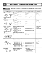
Outlet Thermostat (Manual reset) • Check Top Marking: N100 Test Procedure Measure resistance of terminal to terminal Open at 203 ± 7°F (95 ± 5°C) Close at ... ± 7°C) Manual reset If thermal fuse is open must be replaced Resistance value ∞ Continuity < 1Ω • Gas type • Gas funnel 16 Outlet Thermostat (Auto reset) • Check Top Marking: N95 14. Component 13.
Outlet Thermostat (Manual reset) • Check Top Marking: N100 Test Procedure Measure resistance of terminal to terminal Open at 203 ± 7°F (95 ± 5°C) Close at ... ± 7°C) Manual reset If thermal fuse is open must be replaced Resistance value ∞ Continuity < 1Ω • Gas type • Gas funnel 16 Outlet Thermostat (Auto reset) • Check Top Marking: N95 14. Component 13.
Service Manual
Page 20
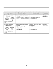
... WH1 TRANS BL2 3 1 TAB RELAY TAB RELAY BLACK WHITE NA6 6 5 432 1 RED WHITE BACK BLUE ORANGE RED YELLOW BLUE BROWN BROWN RED SAFETY THERMOSTAT OUTER COIL INNER COIL COM NO 1 2 GRAY NC 123 DOOR SWITCH WHITE LAMP YELLOW 1 2 3 BELT SWITCH 1 2 3 7 10 MOTOR OVERLOAD ...PROTECTOR BLUE HEATER 2 1 2 1 MOISTURE THERMISTOR SENSOR CENTRIFUGAL SWITCH BLOWER WHITE THERMOSTAT RED RED HI - LIMIT THERMOSTAT GAS DRYER WIRING DIAGRAM POWER CORD L1 BLACK N WHITE GN/YL WHITE 1 WH1 TRANS BL2 3 1 ELECTRONIC CONTROL YL2 1 3 TAB RELAY ...
... WH1 TRANS BL2 3 1 TAB RELAY TAB RELAY BLACK WHITE NA6 6 5 432 1 RED WHITE BACK BLUE ORANGE RED YELLOW BLUE BROWN BROWN RED SAFETY THERMOSTAT OUTER COIL INNER COIL COM NO 1 2 GRAY NC 123 DOOR SWITCH WHITE LAMP YELLOW 1 2 3 BELT SWITCH 1 2 3 7 10 MOTOR OVERLOAD ...PROTECTOR BLUE HEATER 2 1 2 1 MOISTURE THERMISTOR SENSOR CENTRIFUGAL SWITCH BLOWER WHITE THERMOSTAT RED RED HI - LIMIT THERMOSTAT GAS DRYER WIRING DIAGRAM POWER CORD L1 BLACK N WHITE GN/YL WHITE 1 WH1 TRANS BL2 3 1 ELECTRONIC CONTROL YL2 1 3 TAB RELAY ...
Service Manual
Page 21
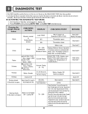
... "SE"(Error Display) Motor, Heater Off Semi-conductor 5 times Control Off During check, If the door is contacted with the Door open may trip the Thermostat attached to the Heater, therefore do not activate it manually. (Do not press the door switch to the step 4. • Press Start 3 times and then...
... "SE"(Error Display) Motor, Heater Off Semi-conductor 5 times Control Off During check, If the door is contacted with the Door open may trip the Thermostat attached to the Heater, therefore do not activate it manually. (Do not press the door switch to the step 4. • Press Start 3 times and then...
Service Manual
Page 26
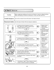
... Does Idle Switch attached to blower housing? NO YES • Replace Control. (Relay check) • Check Controller connector. • Replace Outlet • Thermostat. (Refer to 'Component') • Check Idler Assembly. • Drum Belt cuts off • Drum Belt takes off , and do voltage discharge. ...(When discharging, contact the metal plug of Outlet Thermostat attached to Motor Bracket operate Level by drum belt? YES (Not operating Lever is normal.) Is resistance below 3Ω between terminals of ...
... Does Idle Switch attached to blower housing? NO YES • Replace Control. (Relay check) • Check Controller connector. • Replace Outlet • Thermostat. (Refer to 'Component') • Check Idler Assembly. • Drum Belt cuts off • Drum Belt takes off , and do voltage discharge. ...(When discharging, contact the metal plug of Outlet Thermostat attached to Motor Bracket operate Level by drum belt? YES (Not operating Lever is normal.) Is resistance below 3Ω between terminals of ...
Service Manual
Page 29
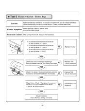
...is below 1Ω between Heater terminal and below 18 ~ 22Ω? 2. TH3 TH2 1. NO YES • Replace TH3 (HI-Limit Thermostat). YES Check Controller. Check Harness-linking Connector. 28 Is resistance between Heater terminal and below 18 ~ 22Ω? 3. Is resistance between terminal... TH3 (HI-Limit Thermostat). NO • Replace Heater. Check Motor. Check if the value of Power cord with earth line.) Trouble Symptom While operating, Heating...
...is below 1Ω between Heater terminal and below 18 ~ 22Ω? 2. TH3 TH2 1. NO YES • Replace TH3 (HI-Limit Thermostat). YES Check Controller. Check Harness-linking Connector. 28 Is resistance between Heater terminal and below 18 ~ 22Ω? 3. Is resistance between terminal... TH3 (HI-Limit Thermostat). NO • Replace Heater. Check Motor. Check if the value of Power cord with earth line.) Trouble Symptom While operating, Heating...
Service Manual
Page 30
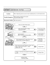
YES NO • Check thermostat Hi limit Safety Igniter operates? (after 1 min, Igniter becomes reddish) YES NO • Check Igniter & Frame detect When measuring Valve 2 voltage, Value is more than1.5 ~ 2....
YES NO • Check thermostat Hi limit Safety Igniter operates? (after 1 min, Igniter becomes reddish) YES NO • Check Igniter & Frame detect When measuring Valve 2 voltage, Value is more than1.5 ~ 2....
Service Manual
Page 44
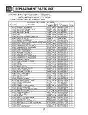
... F200 DUCT ASSEMBLY 3044EL002C 3044EL002C 5209EL1001C 5209EL1001C K250 ROLLER ASSEMBLY F110 HEATER ASSEMBLY 4581EL3001A 4581EL3001A 5301EL1001E 5301EL1001E F130 THERMOSTAT ASSEMBLY F140 THERMOSTAT ASSEMBLY 6931EL3003D 6931EL3003D 6931EL3001E 6931EL3001E A600 HARNESS, PWB K100 TUB ASSEMBLY, DRUM K140 SEAL 6877EL1007A 6877EL1007B 3045EL1002D ... precautions in this manual. ¡Æ Note: S(Safety Parts), AL (Alternative parts) LG MODEL: TD-V10062E, TD-V10060E AL LOC Description Model P/No DLE2512W DLE2514W A500 CABINET ASSEMBLY 3091EL0003A 3091EL0003A K610 MOTOR ASSEMBLY.
... F200 DUCT ASSEMBLY 3044EL002C 3044EL002C 5209EL1001C 5209EL1001C K250 ROLLER ASSEMBLY F110 HEATER ASSEMBLY 4581EL3001A 4581EL3001A 5301EL1001E 5301EL1001E F130 THERMOSTAT ASSEMBLY F140 THERMOSTAT ASSEMBLY 6931EL3003D 6931EL3003D 6931EL3001E 6931EL3001E A600 HARNESS, PWB K100 TUB ASSEMBLY, DRUM K140 SEAL 6877EL1007A 6877EL1007B 3045EL1002D ... precautions in this manual. ¡Æ Note: S(Safety Parts), AL (Alternative parts) LG MODEL: TD-V10062E, TD-V10060E AL LOC Description Model P/No DLE2512W DLE2514W A500 CABINET ASSEMBLY 3091EL0003A 3091EL0003A K610 MOTOR ASSEMBLY.
Service Manual
Page 45
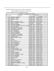
..., read the safety precautions in this manual. ¡Æ Note: S(Safety Parts), AL (Alternative parts) LG MODEL: TD-V10062G,TD-V10060G AL LOC Description Model P/N DLE2522W DLE2524W A500 CABINET ASSEMBLY 3091EL0003B 3091EL0003B A520 BRACKET,... F200 DUCT ASSEMBLY 5209EL1001C 5209EL1001C K250 ROLLER ASSEMBLY 4581EL3001A 4581EL3001A F110 HEATER ASSEMBLY 5301EL1001E 5301EL1001E F130 THERMOSTAT ASSEMBLY 6931EL3003D 6931EL3003D F140 THERMOSTAT ASSEMBLY 6931EL3001E 6931EL3001E A600 HARNESS, PWB 6877EL1008A 6877EL1008A K100 TUB ASSEMBLY, DRUM 3045EL1002D 3045EL1002D K140 SEAL...
..., read the safety precautions in this manual. ¡Æ Note: S(Safety Parts), AL (Alternative parts) LG MODEL: TD-V10062G,TD-V10060G AL LOC Description Model P/N DLE2522W DLE2524W A500 CABINET ASSEMBLY 3091EL0003B 3091EL0003B A520 BRACKET,... F200 DUCT ASSEMBLY 5209EL1001C 5209EL1001C K250 ROLLER ASSEMBLY 4581EL3001A 4581EL3001A F110 HEATER ASSEMBLY 5301EL1001E 5301EL1001E F130 THERMOSTAT ASSEMBLY 6931EL3003D 6931EL3003D F140 THERMOSTAT ASSEMBLY 6931EL3001E 6931EL3001E A600 HARNESS, PWB 6877EL1008A 6877EL1008A K100 TUB ASSEMBLY, DRUM 3045EL1002D 3045EL1002D K140 SEAL...


