Specification
Page 1
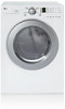
D L E 2 516 D L G 2 5 2 6 L A U N D RY ELECTRIC/GAS DRYERS D L E 2516 DLG2526 Performance • Super Capacity (7.0 cu.ft.) • LoDecibel™ Quiet System Intelligent Fabric Care • Sensor Dry System for intelligent fabric care and energy efficiency • 5 Drying Programs • 5 Temperature Levels • Wrinkle Care Option • Delicates Cycle Style and Design • Upfront Electronic Control Panel with Dial-A-Cycle™ • Silver Rimmed Door with Clear Glass • Stackable with Matching Washer • Optional Drawer Pedestals White LGusa.com
D L E 2 516 D L G 2 5 2 6 L A U N D RY ELECTRIC/GAS DRYERS D L E 2516 DLG2526 Performance • Super Capacity (7.0 cu.ft.) • LoDecibel™ Quiet System Intelligent Fabric Care • Sensor Dry System for intelligent fabric care and energy efficiency • 5 Drying Programs • 5 Temperature Levels • Wrinkle Care Option • Delicates Cycle Style and Design • Upfront Electronic Control Panel with Dial-A-Cycle™ • Silver Rimmed Door with Clear Glass • Stackable with Matching Washer • Optional Drawer Pedestals White LGusa.com
Specification
Page 2
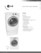
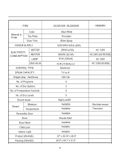
... DIMENSIONS Product (WxHxD) 27" x 38 3/4" x 29 15/16" (49 3/4"D with door open) Carton (WxHxD) 29 1/2" x 43" x 31 1/4" Weight (lbs): Net / Shipping 126 / 144 WA R R A N T Y 1 Year Labor and Parts UPC CODE DLE2516W 048231 009096 DLG2526W 048231 009102 WDP3W 048231 008556 WSTK1 048231 008327 Design and specifications are periodically... min., 40 min., 30 min., 20 min., More Time/Less Time FABRIC CARE FEATURES Sensor Dry CONVENIENCE FEATURES End of LG Electronics Inc. Wrinkle Care Cycle Dry clothes are subject to change without heat to "set it and go". Sensor Dry System...
... DIMENSIONS Product (WxHxD) 27" x 38 3/4" x 29 15/16" (49 3/4"D with door open) Carton (WxHxD) 29 1/2" x 43" x 31 1/4" Weight (lbs): Net / Shipping 126 / 144 WA R R A N T Y 1 Year Labor and Parts UPC CODE DLE2516W 048231 009096 DLG2526W 048231 009102 WDP3W 048231 008556 WSTK1 048231 008327 Design and specifications are periodically... min., 40 min., 30 min., 20 min., More Time/Less Time FABRIC CARE FEATURES Sensor Dry CONVENIENCE FEATURES End of LG Electronics Inc. Wrinkle Care Cycle Dry clothes are subject to change without heat to "set it and go". Sensor Dry System...
Service Manual
Page 4
CONTROL LAYOUT ...18 8. DIAGNOSTIC TEST ...20 9-1. TEST 4 MOISTURE SENSOR 26 9-5. TEST 7 GAS VALVE TEST - CABINET & DOOR ASSEMBLY 40 12-3-1. WIRING DIAGRAM ...19 9. TEST 2 THERMISTOR TEST 24 9-3. ELECTRIC MODEL 28 9-7. DISASSEMBLY INSTRUCTIONS 32 12. EXPLODED VIEW ...39 12... ...13 5. CHANGE GAS SETTING (NATURAL GAS, PROPANE GAS 30 11. CONTENTS 1. SPECIFICATIONS ...4 2. DRUM & MOTOR ASSEMBLY: ELECTRIC MODEL 41 12-3-2. TEST 5 DOOR SWITCH TEST 27 9-6. INSTALLATION INSTRUCTIONS 6 4. TEST 3 MOTOR TEST 25 9-4. GAS MODEL 29 10. FEATURES AND BENEFITS ...6 3.
CONTROL LAYOUT ...18 8. DIAGNOSTIC TEST ...20 9-1. TEST 4 MOISTURE SENSOR 26 9-5. TEST 7 GAS VALVE TEST - CABINET & DOOR ASSEMBLY 40 12-3-1. WIRING DIAGRAM ...19 9. TEST 2 THERMISTOR TEST 24 9-3. ELECTRIC MODEL 28 9-7. DISASSEMBLY INSTRUCTIONS 32 12. EXPLODED VIEW ...39 12... ...13 5. CHANGE GAS SETTING (NATURAL GAS, PROPANE GAS 30 11. CONTENTS 1. SPECIFICATIONS ...4 2. DRUM & MOTOR ASSEMBLY: ELECTRIC MODEL 41 12-3-2. TEST 5 DOOR SWITCH TEST 27 9-6. INSTALLATION INSTRUCTIONS 6 4. TEST 3 MOTOR TEST 25 9-4. GAS MODEL 29 10. FEATURES AND BENEFITS ...6 3.
Service Manual
Page 6
... VALVE CONTROL TYPE DRUM CAPACITY Weight (lbs) - of Dry Options No. of Dry Levels Sound levels Sensor Moisture Temperature Reversible Door Drum Dryer Rack Child Lock Interior Light Product (WxHxD) Packing (WxHxD) DLE2516W / DLG2526W Blue White Porcelain Silver Spray 120V/240V 60Hz (26A) 250W (4.5A) 5400W (22.5A) 15 W (125mA) 13 W (110mA...
... VALVE CONTROL TYPE DRUM CAPACITY Weight (lbs) - of Dry Options No. of Dry Levels Sound levels Sensor Moisture Temperature Reversible Door Drum Dryer Rack Child Lock Interior Light Product (WxHxD) Packing (WxHxD) DLE2516W / DLG2526W Blue White Porcelain Silver Spray 120V/240V 60Hz (26A) 250W (4.5A) 5400W (22.5A) 15 W (125mA) 13 W (110mA...
Service Manual
Page 7
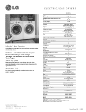
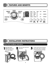
2 FEATURES AND BENEFITS 3 INSTALLATION INSTRUCTIONS Dryer Rack Installation Instructions 1Open the door. Hold the dryer rack with both hands. 2 Put the dryer rack into the drum 3 Check and be sure that the front of the rack is properly seated behind the lint filter. 6
2 FEATURES AND BENEFITS 3 INSTALLATION INSTRUCTIONS Dryer Rack Installation Instructions 1Open the door. Hold the dryer rack with both hands. 2 Put the dryer rack into the drum 3 Check and be sure that the front of the rack is properly seated behind the lint filter. 6
Service Manual
Page 15
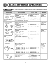
...Auto reset) • Check Top Marking: N85 4. Resistance value ∞ Resistance value < 5Ω Measure resistance of the following terminal 1) Door switch knob: open Resistance value < 1Ω 2. NC" 1. 5 COMPONENT TESTING INFORMATION ! Component 1. to terminal be sure to terminal 80...; • Heater case Hi limit • Electric type • Blow housing Safety • Electric type 5. lever open Terminal: "COM" - Door switch 6. "NC" (1-3) Terminal: "COM" - "NC" (1-3) Terminal: "COM" - Measure resistance of terminal Resistance value: to turn the power...
...Auto reset) • Check Top Marking: N85 4. Resistance value ∞ Resistance value < 5Ω Measure resistance of the following terminal 1) Door switch knob: open Resistance value < 1Ω 2. NC" 1. 5 COMPONENT TESTING INFORMATION ! Component 1. to terminal be sure to terminal 80...; • Heater case Hi limit • Electric type • Blow housing Safety • Electric type 5. lever open Terminal: "COM" - Door switch 6. "NC" (1-3) Terminal: "COM" - "NC" (1-3) Terminal: "COM" - Measure resistance of terminal Resistance value: to turn the power...
Service Manual
Page 20
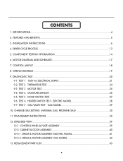
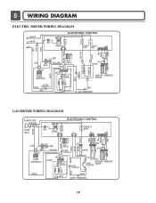
... 3 TAB RELAY BLACK BL3 123 NA6 6 5 4321 RED PINK WHITE BLUE ORANGE RED BLUE BLUE BROWN BROWN COM 1 2 NO GRAY NC 123 DOOR SWITCH LAMP YELLOW 1 2 3 BELT SWITCH BLOWER THERMOSTAT GRAY BLUE RED 23 1212 IGNITER BLUE 21 21 YELLOW MOTOR 2379 OVERLOAD PROTECTOR HI-LIMIT THERMOSTAT... 5 432 1 RED WHITE BACK BLUE ORANGE RED YELLOW BLUE BROWN BROWN RED SAFETY THERMOSTAT OUTER COIL INNER COIL COM NO 1 2 GRAY NC 123 DOOR SWITCH WHITE LAMP YELLOW 1 2 3 BELT SWITCH 1 2 3 7 10 MOTOR OVERLOAD PROTECTOR BLUE HEATER 2 1 2 1 MOISTURE THERMISTOR SENSOR CENTRIFUGAL SWITCH BLOWER ...
... 3 TAB RELAY BLACK BL3 123 NA6 6 5 4321 RED PINK WHITE BLUE ORANGE RED BLUE BLUE BROWN BROWN COM 1 2 NO GRAY NC 123 DOOR SWITCH LAMP YELLOW 1 2 3 BELT SWITCH BLOWER THERMOSTAT GRAY BLUE RED 23 1212 IGNITER BLUE 21 21 YELLOW MOTOR 2379 OVERLOAD PROTECTOR HI-LIMIT THERMOSTAT... 5 432 1 RED WHITE BACK BLUE ORANGE RED YELLOW BLUE BROWN BROWN RED SAFETY THERMOSTAT OUTER COIL INNER COIL COM NO 1 2 GRAY NC 123 DOOR SWITCH WHITE LAMP YELLOW 1 2 3 BELT SWITCH 1 2 3 7 10 MOTOR OVERLOAD PROTECTOR BLUE HEATER 2 1 2 1 MOISTURE THERMISTOR SENSOR CENTRIFUGAL SWITCH BLOWER ...
Service Manual
Page 21
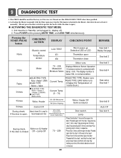
...drum.) 4 times Motor, Heater 50~230 Measured "SE"(Error Display) Motor, Heater Off Semi-conductor 5 times Control Off During check, If the door is open the door. Off + Lamp Off 70 ~ 239 • Press Start button 1 time and then open ) ACTIVATING THE DIAGNOSTIC TEST MODE 1. Proceed again ... pressing start 2 times), step 3 (by pressing start 3 times) and step 4 (by making sure the all the way to operate the heater while the door is open Thermistor close See test 1 Display: See page See test 2 Once Motor Motor runs 70 ~ 239 Measured Moisture Value. Motor & Heater Off + ...
...drum.) 4 times Motor, Heater 50~230 Measured "SE"(Error Display) Motor, Heater Off Semi-conductor 5 times Control Off During check, If the door is open the door. Off + Lamp Off 70 ~ 239 • Press Start button 1 time and then open ) ACTIVATING THE DIAGNOSTIC TEST MODE 1. Proceed again ... pressing start 2 times), step 3 (by pressing start 3 times) and step 4 (by making sure the all the way to operate the heater while the door is open Thermistor close See test 1 Display: See page See test 2 Once Motor Motor runs 70 ~ 239 Measured Moisture Value. Motor & Heater Off + ...
Service Manual
Page 26
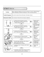
... Heater will function; NO Is resistance below 3Ω between Connector BL2- (Yellow wire) and BL2- (Brown wire)? Measure while door is contacted. 25 Is resistance below 3Ω between terminals of Power cord with earth line.) Trouble Symptom Drum will not rotate;...Bracket operate Level by drum belt? NO YES Is resistance below 1Ω between Connector WH (White wire) and BL2- (Brown wire)? Measure while door is normal.) Is resistance below 1Ω between Connector WH (White wire) and BL2- (Yellow wire)? No fan will work. Measurement Condition Turn the...
... Heater will function; NO Is resistance below 3Ω between Connector BL2- (Yellow wire) and BL2- (Brown wire)? Measure while door is contacted. 25 Is resistance below 3Ω between terminals of Power cord with earth line.) Trouble Symptom Drum will not rotate;...Bracket operate Level by drum belt? NO YES Is resistance below 1Ω between Connector WH (White wire) and BL2- (Brown wire)? Measure while door is normal.) Is resistance below 1Ω between Connector WH (White wire) and BL2- (Yellow wire)? No fan will work. Measurement Condition Turn the...
Service Manual
Page 28
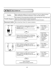
... 1 Ω between BL2- (Yellow wire) and WH1- (White wire) after taking Connector WH1,BL2 NO out from Controller. Test 5 Door switch test Caution Before measuring resistance, be sure to turn Power off, and do voltage discharge. (When discharging, contact the metal plug of ...Power cord with earth line.) Door Opening is not sensed.(During operation, when opening Lamp, replace then measure again.) • Door switch Check(Refer to Component testing.) Check Controller. Check it resistance is below 2500 Ω...
... 1 Ω between BL2- (Yellow wire) and WH1- (White wire) after taking Connector WH1,BL2 NO out from Controller. Test 5 Door switch test Caution Before measuring resistance, be sure to turn Power off, and do voltage discharge. (When discharging, contact the metal plug of ...Power cord with earth line.) Door Opening is not sensed.(During operation, when opening Lamp, replace then measure again.) • Door switch Check(Refer to Component testing.) Check Controller. Check it resistance is below 2500 Ω...
Service Manual
Page 35
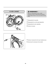
Remove 4 screws from the top of door switch. 34 When you disassemble the door switch connector, be sure to do so can cause serious injury. 1. Disassemble the door assembly. 4. COVER CABINET ! Disconnect the harness of cabinet cover. 6. Disassemble the top plate. 2. Failure to take gloves and careful cabinet edge. Remove 2 screws. 5. Disassemble the control panel assembly. 3. WARNING !
Remove 4 screws from the top of door switch. 34 When you disassemble the door switch connector, be sure to do so can cause serious injury. 1. Disassemble the door assembly. 4. COVER CABINET ! Disconnect the harness of cabinet cover. 6. Disassemble the top plate. 2. Failure to take gloves and careful cabinet edge. Remove 2 screws. 5. Disassemble the control panel assembly. 3. WARNING !

Service Manual
Page 36
... the top plate. 2. Failure to take gloves and careful cabinet edge. Remove the Cabinet Cover and Tub drum [front]. 3. Disconnect the door lamp and electrode sensor connector. 4. Disassemble the Tub Drum [Front]. 1. Remove the bulb and replace with a 15 watt, 120 volt candelabra-base bulb. 5. Loosen belt ...
... the top plate. 2. Failure to take gloves and careful cabinet edge. Remove the Cabinet Cover and Tub drum [front]. 3. Disconnect the door lamp and electrode sensor connector. 4. Disassemble the Tub Drum [Front]. 1. Remove the bulb and replace with a 15 watt, 120 volt candelabra-base bulb. 5. Loosen belt ...
Service Manual
Page 44
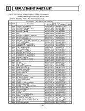
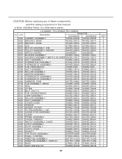
...3211EL1005A 3211EL1005A K620 K350 A310 A330 CLAMP CONNECTOR ASSEMBLY COVER, CABINET SWITCH ASSEMBLY, DOOR 4860EL3001A 6631EL3003B 3550EL0006A 6601EL3001A 4860EL3001A 6631EL3003B 3550EL0006A 6601EL3001A A320 LATCH ASSEMBLY A400 DOOR ASSEMBLY 4027EL1001A 4027EL1001A 3581EL0003B 3581EL0003A A410 LATCH, HOOK A460 GASKET A210 TOP PLATE ... the safety precautions in this manual. ¡Æ Note: S(Safety Parts), AL (Alternative parts) LG MODEL: TD-V10062E, TD-V10060E AL LOC Description Model P/No DLE2512W DLE2514W A500 CABINET ASSEMBLY 3091EL0003A 3091EL0003A K610 MOTOR ASSEMBLY.
...3211EL1005A 3211EL1005A K620 K350 A310 A330 CLAMP CONNECTOR ASSEMBLY COVER, CABINET SWITCH ASSEMBLY, DOOR 4860EL3001A 6631EL3003B 3550EL0006A 6601EL3001A 4860EL3001A 6631EL3003B 3550EL0006A 6601EL3001A A320 LATCH ASSEMBLY A400 DOOR ASSEMBLY 4027EL1001A 4027EL1001A 3581EL0003B 3581EL0003A A410 LATCH, HOOK A460 GASKET A210 TOP PLATE ... the safety precautions in this manual. ¡Æ Note: S(Safety Parts), AL (Alternative parts) LG MODEL: TD-V10062E, TD-V10060E AL LOC Description Model P/No DLE2512W DLE2514W A500 CABINET ASSEMBLY 3091EL0003A 3091EL0003A K610 MOTOR ASSEMBLY.
Service Manual
Page 45
..., read the safety precautions in this manual. ¡Æ Note: S(Safety Parts), AL (Alternative parts) LG MODEL: TD-V10062G,TD-V10060G AL LOC Description Model P/N DLE2522W DLE2524W A500 CABINET ASSEMBLY 3091EL0003B 3091EL0003B A520 BRACKET,...4860EL3001A A390 FRAME ASSEMBLY 3211EL1005A 3211EL1005A A310 COVER, CABINET 3550EL0006A 3550EL0006A A330 SWITCH ASSEMBLY, DOOR 6601EL3001A 6601EL3001A A320 LATCH ASSEMBLY 4027EL1001A 4027EL1001A A400 DOOR ASSEMBLY 3581EL0003B 3581EL0003A A410 LATCH, HOOK 4026EL3007A 4026EL3007A A460 GASKET 4986EL2004D 4986EL2004D A210 TOP...
..., read the safety precautions in this manual. ¡Æ Note: S(Safety Parts), AL (Alternative parts) LG MODEL: TD-V10062G,TD-V10060G AL LOC Description Model P/N DLE2522W DLE2524W A500 CABINET ASSEMBLY 3091EL0003B 3091EL0003B A520 BRACKET,...4860EL3001A A390 FRAME ASSEMBLY 3211EL1005A 3211EL1005A A310 COVER, CABINET 3550EL0006A 3550EL0006A A330 SWITCH ASSEMBLY, DOOR 6601EL3001A 6601EL3001A A320 LATCH ASSEMBLY 4027EL1001A 4027EL1001A A400 DOOR ASSEMBLY 3581EL0003B 3581EL0003A A410 LATCH, HOOK 4026EL3007A 4026EL3007A A460 GASKET 4986EL2004D 4986EL2004D A210 TOP...
Owners Manual
Page 2
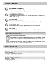
...Time Dry Use TIME DRY to guarantee high durability and the long life. 3 ARTISTIC DESIGN Modern front panel look and big crystal-clear glass door make your house look stylish. 4 DIGITAL FABRIC CARE Multi-level temperature control heater takes a better care on your valued clothes. 5 EASY ...dry as you like them at the end of the laundry and automatically determines the heat level and operation time. TROUBLESHOOTING GUIDE...28 LG DRYER LIMITED WARRANTY...31 2 ELECTRICAL REQUIREMENTS FOR GAS DRYERS...18 PART 7. PRODUCT FEATURES 1 OUTSTANDING PERFORMANCE Not to mention unmatched big capacity...
...Time Dry Use TIME DRY to guarantee high durability and the long life. 3 ARTISTIC DESIGN Modern front panel look and big crystal-clear glass door make your house look stylish. 4 DIGITAL FABRIC CARE Multi-level temperature control heater takes a better care on your valued clothes. 5 EASY ...dry as you like them at the end of the laundry and automatically determines the heat level and operation time. TROUBLESHOOTING GUIDE...28 LG DRYER LIMITED WARRANTY...31 2 ELECTRICAL REQUIREMENTS FOR GAS DRYERS...18 PART 7. PRODUCT FEATURES 1 OUTSTANDING PERFORMANCE Not to mention unmatched big capacity...
Owners Manual
Page 4
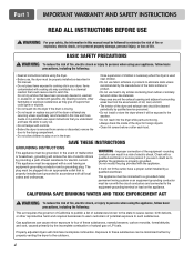
... rubber or similarly textured rubber-like materials. • Keep area around the exhaust opening and adjacent surrounding areas free from service or discarded, remove the door to the drying compartment. • Do not allow children to the equipment-grounding terminal or lead on or in the dryer. This appliance must be...
... rubber or similarly textured rubber-like materials. • Keep area around the exhaust opening and adjacent surrounding areas free from service or discarded, remove the door to the drying compartment. • Do not allow children to the equipment-grounding terminal or lead on or in the dryer. This appliance must be...
Owners Manual
Page 9
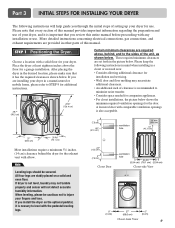
... 9 for additional instructions. 38.7" (98.3 cm) 49.8" (126.4 cm) Certain minimum clearances are required above the floor for the door. All four legs are installing your dryer, and it is recommended to the sides of your dryer in a closet or recessed area: ...parts of this manual provides important information regarding the preparation and use . ventilation hole ventilation hole Closet Door Closet-side View Closet-front View 9 STEP 1 Positioning the Dryer. A louvered door with comparable ventilation openings is also acceptable. 27" (68.6 cm) 29.96" (76.1 cm...
... 9 for additional instructions. 38.7" (98.3 cm) 49.8" (126.4 cm) Certain minimum clearances are required above the floor for the door. All four legs are installing your dryer, and it is recommended to the sides of your dryer in a closet or recessed area: ...parts of this manual provides important information regarding the preparation and use . ventilation hole ventilation hole Closet Door Closet-side View Closet-front View 9 STEP 1 Positioning the Dryer. A louvered door with comparable ventilation openings is also acceptable. 27" (68.6 cm) 29.96" (76.1 cm...
Owners Manual
Page 10
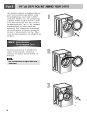
If the dryer is level from left or the right. The leveling legs must remain firmly on your door opens: Note Door and latch should be installed to open either to the left to right or front to back should not rock. Part 3 INITIAL STEPS FOR INSTALLING ... of the dryer from left to right and front to reverse the direction in position, adjust the leveling legs of and clearances for Reversing the Door The door on the floor and the dryer should not exceed 1 inch (2.5 cm). Please review this manual also provide important information concerning the placement of the...
If the dryer is level from left or the right. The leveling legs must remain firmly on your door opens: Note Door and latch should be installed to open either to the left to right or front to back should not rock. Part 3 INITIAL STEPS FOR INSTALLING ... of the dryer from left to right and front to reverse the direction in position, adjust the leveling legs of and clearances for Reversing the Door The door on the floor and the dryer should not exceed 1 inch (2.5 cm). Please review this manual also provide important information concerning the placement of the...
Owners Manual
Page 13
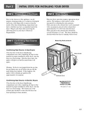
...If all air is running with damp cloth to the dryer drum/drying compartment and, after completing all steps in Gas Dryers Close the door to the first use allpurpose cleaning products or a solution of the Dryer. Confirming Heat Source in this manual for proper installation of ...pipe should not exceed 5/8 inches (1.5 cm). Plug-in the exhaust duct can be warm after completing all steps in Electric Dryers Close the door to remove from the dryer. Measuring Static pressure Confirming Heat Source in this manual for three minutes. 1 Manometer 2 Exhaust Duct MAXIMUM STATIC ...
...If all air is running with damp cloth to the dryer drum/drying compartment and, after completing all steps in Gas Dryers Close the door to the first use allpurpose cleaning products or a solution of the Dryer. Confirming Heat Source in this manual for proper installation of ...pipe should not exceed 5/8 inches (1.5 cm). Plug-in the exhaust duct can be warm after completing all steps in Electric Dryers Close the door to remove from the dryer. Measuring Static pressure Confirming Heat Source in this manual for three minutes. 1 Manometer 2 Exhaust Duct MAXIMUM STATIC ...
Owners Manual
Page 26
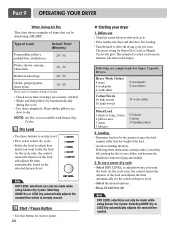
... be made while using Sensor Dry Cycles. To use • Clean lint screen before or after each cycle. • Place laundry into dryer and shut door. Loading • Determine load size by hand periodically during the cycle. • Dry item completely. As the cycle runs, the control senses the dryness of...
... be made while using Sensor Dry Cycles. To use • Clean lint screen before or after each cycle. • Place laundry into dryer and shut door. Loading • Determine load size by hand periodically during the cycle. • Dry item completely. As the cycle runs, the control senses the dryness of...


