Specification
Page 1
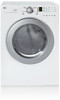
D L E 2 516 D L G 2 5 2 6 L A U N D RY ELECTRIC/GAS DRYERS D L E 2516 DLG2526 Performance • Super Capacity (7.0 cu.ft.) • LoDecibel™ Quiet System Intelligent Fabric Care • Sensor Dry System for intelligent fabric care and energy efficiency • 5 Drying Programs • 5 Temperature Levels • Wrinkle Care Option • Delicates Cycle Style and Design • Upfront Electronic Control Panel with Dial-A-Cycle™ • Silver Rimmed Door with Clear Glass • Stackable with Matching Washer • Optional Drawer Pedestals White LGusa.com
D L E 2 516 D L G 2 5 2 6 L A U N D RY ELECTRIC/GAS DRYERS D L E 2516 DLG2526 Performance • Super Capacity (7.0 cu.ft.) • LoDecibel™ Quiet System Intelligent Fabric Care • Sensor Dry System for intelligent fabric care and energy efficiency • 5 Drying Programs • 5 Temperature Levels • Wrinkle Care Option • Delicates Cycle Style and Design • Upfront Electronic Control Panel with Dial-A-Cycle™ • Silver Rimmed Door with Clear Glass • Stackable with Matching Washer • Optional Drawer Pedestals White LGusa.com
Specification
Page 2
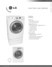
...Less Time FABRIC CARE FEATURES Sensor Dry CONVENIENCE FEATURES End of LG Electronics Inc. LG ELECTRONICS INC. 1000 Sylvan Ave., Englewood Cliffs, NJ 07632 800.243.0000 LGusa.com ELECTRIC/GAS DRYERS DLE2516 DLG2526 TYPE Design Look Front Control Intelligent Electronic Controls with ...Carton (WxHxD) 29 1/2" x 43" x 31 1/4" Weight (lbs): Net / Shipping 126 / 144 WA R R A N T Y 1 Year Labor and Parts UPC CODE DLE2516W 048231 009096 DLG2526W 048231 009102 WDP3W 048231 008556 WSTK1 048231 008327 Design and specifications are periodically tumbled without notice. ©2008...
...Less Time FABRIC CARE FEATURES Sensor Dry CONVENIENCE FEATURES End of LG Electronics Inc. LG ELECTRONICS INC. 1000 Sylvan Ave., Englewood Cliffs, NJ 07632 800.243.0000 LGusa.com ELECTRIC/GAS DRYERS DLE2516 DLG2526 TYPE Design Look Front Control Intelligent Electronic Controls with ...Carton (WxHxD) 29 1/2" x 43" x 31 1/4" Weight (lbs): Net / Shipping 126 / 144 WA R R A N T Y 1 Year Labor and Parts UPC CODE DLE2516W 048231 009096 DLG2526W 048231 009102 WDP3W 048231 008556 WSTK1 048231 008327 Design and specifications are periodically tumbled without notice. ©2008...
Service Manual
Page 1
U.S.A. MODEL : DLE2516W/DLG2526W/DLE3733 Website: http://us.lgservice.com Canadian Website: http://lg.ca ELECTRIC & GAS DRYER SERVICE MANUAL CAUTION READ THIS MANUAL CAREFULLY IN ORDER TO PROPERLY DIAGNOSE PROBLEMS AND TO SAFELY PROVIDE QUALITY SERVICE ON THESE DRYERS.
U.S.A. MODEL : DLE2516W/DLG2526W/DLE3733 Website: http://us.lgservice.com Canadian Website: http://lg.ca ELECTRIC & GAS DRYER SERVICE MANUAL CAUTION READ THIS MANUAL CAREFULLY IN ORDER TO PROPERLY DIAGNOSE PROBLEMS AND TO SAFELY PROVIDE QUALITY SERVICE ON THESE DRYERS.
Service Manual
Page 4
... MODEL 29 10. CABINET & DOOR ASSEMBLY 40 12-3-1. COMPONENT TESTING INFORMATION 14 6. EXPLODED VIEW ...39 12-1. REPLACEMENT PARTS LIST 43 3 FEATURES AND BENEFITS ...6 3. INSTALLATION INSTRUCTIONS 6 4. DRYER CYCLE PROCESS ...13 5. MOTOR DIAGRAM AND SCHEMATIC 17 7. CONTROL LAYOUT ...18 8. TEST 4 MOISTURE SENSOR 26 9-5. TEST 5 DOOR SWITCH TEST 27 9-6. ELECTRIC MODEL 28 9-7. TEST 7 GAS...
... MODEL 29 10. CABINET & DOOR ASSEMBLY 40 12-3-1. COMPONENT TESTING INFORMATION 14 6. EXPLODED VIEW ...39 12-1. REPLACEMENT PARTS LIST 43 3 FEATURES AND BENEFITS ...6 3. INSTALLATION INSTRUCTIONS 6 4. DRYER CYCLE PROCESS ...13 5. MOTOR DIAGRAM AND SCHEMATIC 17 7. CONTROL LAYOUT ...18 8. TEST 4 MOISTURE SENSOR 26 9-5. TEST 5 DOOR SWITCH TEST 27 9-6. ELECTRIC MODEL 28 9-7. TEST 7 GAS...
Service Manual
Page 5
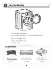
1 SPECIFICATIONS I Name: Electric and Gas Dryer I Power supply: Please refer to change by manufacturer. I Size: 27 X 29.9 X 38.7 (inch) I ACCESSORIES Dryer rack (1 each) Purchased Separately See page 6 Stacking kit (1 each) Purchased Separately See page 7 4 Pedestal (1 each) Purchased Separately See page 8 I Dryer capacity: IEC 7.3 cu.ft. I Weight: 126(Ibs) Specifications are subject to the rating label regarding detailed information.
1 SPECIFICATIONS I Name: Electric and Gas Dryer I Power supply: Please refer to change by manufacturer. I Size: 27 X 29.9 X 38.7 (inch) I ACCESSORIES Dryer rack (1 each) Purchased Separately See page 6 Stacking kit (1 each) Purchased Separately See page 7 4 Pedestal (1 each) Purchased Separately See page 8 I Dryer capacity: IEC 7.3 cu.ft. I Weight: 126(Ibs) Specifications are subject to the rating label regarding detailed information.
Service Manual
Page 6
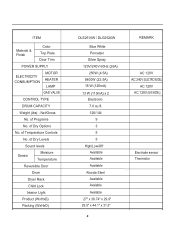
... CAPACITY Weight (lbs) - of Dry Options No. Net/Gross No. of Dry Levels Sound levels Sensor Moisture Temperature Reversible Door Drum Dryer Rack Child Lock Interior Light Product (WxHxD) Packing (WxHxD) DLE2516W / DLG2526W Blue White Porcelain Silver Spray 120V/240V 60Hz (26A) 250W (4.5A) 5400W (22.5A) 15 W (125mA) 13 W (110mA) x 2 Electronic...
... CAPACITY Weight (lbs) - of Dry Options No. Net/Gross No. of Dry Levels Sound levels Sensor Moisture Temperature Reversible Door Drum Dryer Rack Child Lock Interior Light Product (WxHxD) Packing (WxHxD) DLE2516W / DLG2526W Blue White Porcelain Silver Spray 120V/240V 60Hz (26A) 250W (4.5A) 5400W (22.5A) 15 W (125mA) 13 W (110mA) x 2 Electronic...
Service Manual
Page 7
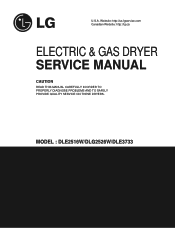
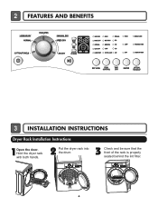
Hold the dryer rack with both hands. 2 Put the dryer rack into the drum 3 Check and be sure that the front of the rack is properly seated behind the lint filter. 6 2 FEATURES AND BENEFITS 3 INSTALLATION INSTRUCTIONS Dryer Rack Installation Instructions 1Open the door.
Hold the dryer rack with both hands. 2 Put the dryer rack into the drum 3 Check and be sure that the front of the rack is properly seated behind the lint filter. 6 2 FEATURES AND BENEFITS 3 INSTALLATION INSTRUCTIONS Dryer Rack Installation Instructions 1Open the door.
Service Manual
Page 8
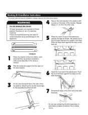
... like a mobile home. 7 Repeat Steps 2, 3, & 4 for the other side. At least two people are required to pinch fingers between the washer and dryer. Push the front rail back against the stop on the side rail. 1 2 Stacking kit Place the washer firmly on the side brackets. 3 Fit the side.... Stacking Kit Installation Instructions To ensure safe and secure installation, please observe the instructions below. Be careful not to lift and position the dryer on the back of a washing machine! Peel the protective paper from the tape on top of the washer by attaching the double-faced ...
... like a mobile home. 7 Repeat Steps 2, 3, & 4 for the other side. At least two people are required to pinch fingers between the washer and dryer. Push the front rail back against the stop on the side rail. 1 2 Stacking kit Place the washer firmly on the side brackets. 3 Fit the side.... Stacking Kit Installation Instructions To ensure safe and secure installation, please observe the instructions below. Be careful not to lift and position the dryer on the back of a washing machine! Peel the protective paper from the tape on top of the washer by attaching the double-faced ...
Service Manual
Page 9
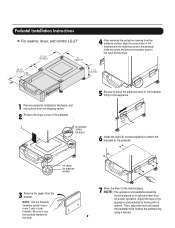
... and pedestal assembly must be placed on top of the pedestal. , for washer/ combo for dryer . NOTE: That the Pedestal hardware packet may include 2 sets of the appliance and pedestal by... while holding the pedestal leg using a wrench. 8 Pedestal Installation Instructions For washer, dryer, and combo LG 27" 4 AAtftaecr hretmheovdinogubthle-pfarocteedcttivaepecoovfetrhinegbfroamcktehteto the dardyheersaivsesshuorfwacnes, oaltighne tbhenstcpreawrtshoolfetshien bthreackets ablriagcnkwetisthwtihthetheedgmeaatcnhdincgahnoblees aintttahcehpeeddteostahle pbeadseesatnadl wpritehssscarnedwpsr....
... and pedestal assembly must be placed on top of the pedestal. , for washer/ combo for dryer . NOTE: That the Pedestal hardware packet may include 2 sets of the appliance and pedestal by... while holding the pedestal leg using a wrench. 8 Pedestal Installation Instructions For washer, dryer, and combo LG 27" 4 AAtftaecr hretmheovdinogubthle-pfarocteedcttivaepecoovfetrhinegbfroamcktehteto the dardyheersaivsesshuorfwacnes, oaltighne tbhenstcpreawrtshoolfetshien bthreackets ablriagcnkwetisthwtihthetheedgmeaatcnhdincgahnoblees aintttahcehpeeddteostahle pbeadseesatnadl wpritehssscarnedwpsr....
Service Manual
Page 10
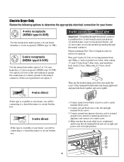
... ground to center terminal block screw. 2. Make sure that all terminal block nuts are on tight and power cord is in order for dryer to be replaced. Electric Dryer Only Review the following options to determine the appropriate electrical connection for (1) new branch-circuit installations, (2) mobile homes, and (3) recreational vehicles, and (4) areas...
... ground to center terminal block screw. 2. Make sure that all terminal block nuts are on tight and power cord is in order for dryer to be replaced. Electric Dryer Only Review the following options to determine the appropriate electrical connection for (1) new branch-circuit installations, (2) mobile homes, and (3) recreational vehicles, and (4) areas...
Service Manual
Page 11
...Power supply cord. • lf your local codes or ordinances do not allow the use of a 3 wire connection, or you are installing your dryer in the right position. Connect neutral wire(white) of the power B cord to center screw. 4. Connect the neutral wire (white) of power ...-circuit installations, (2) mobile homes, and (3) recreational vehicles, and (4) areas where local codes prohibit grounding through the neutral conductor is prohibited for cm) dryer to be sure that all terminal block nuts are tight and the power cord is in a mobile home, you must use a 4wire connection. 1....
...Power supply cord. • lf your local codes or ordinances do not allow the use of a 3 wire connection, or you are installing your dryer in the right position. Connect neutral wire(white) of the power B cord to center screw. 4. Connect the neutral wire (white) of power ...-circuit installations, (2) mobile homes, and (3) recreational vehicles, and (4) areas where local codes prohibit grounding through the neutral conductor is prohibited for cm) dryer to be sure that all terminal block nuts are tight and the power cord is in a mobile home, you must use a 4wire connection. 1....
Service Manual
Page 13
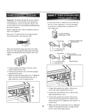
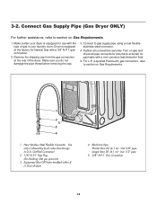
Use only if allowed by local codes (Use Design A.G.A. 3-2. Connect Gas Supply Pipe (Gas Dryer ONLY) For further assistance, refer to section on Gas Requirements. 1 2 5 3 4 1 New Stainless Steel Flexible Connector - Gas Connection 12 Make certain your laundry room... supply pipe using a new flexible stainless steel connector. 4. Pipe Plug (for use with the type of gas in your dryer is equipped at the rear of dryer 4 Black Iron Pipe Shorter than 20' (6.1 m) - Dryer is equipped for checking inlet gas pressure) 3 Equipment Shut-Off Valve-Installed within 6' (1.8 m) of the...
Use only if allowed by local codes (Use Design A.G.A. 3-2. Connect Gas Supply Pipe (Gas Dryer ONLY) For further assistance, refer to section on Gas Requirements. 1 2 5 3 4 1 New Stainless Steel Flexible Connector - Gas Connection 12 Make certain your laundry room... supply pipe using a new flexible stainless steel connector. 4. Pipe Plug (for use with the type of gas in your dryer is equipped at the rear of dryer 4 Black Iron Pipe Shorter than 20' (6.1 m) - Dryer is equipped for checking inlet gas pressure) 3 Equipment Shut-Off Valve-Installed within 6' (1.8 m) of the...
Service Manual
Page 14
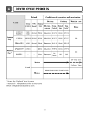
Default settings can be adjusted by users. Temp- Dry Display erature Level time Electro- 4 DRYER CYCLE PROCESS Default Conditions of operation and termination Cycle Drying Cooling Wrinkle care Temp- Default Tempsensor Control time Control** Time COTTON/ TOWELS MID HIGH (Normal) ...
Default settings can be adjusted by users. Temp- Dry Display erature Level time Electro- 4 DRYER CYCLE PROCESS Default Conditions of operation and termination Cycle Drying Cooling Wrinkle care Temp- Default Tempsensor Control time Control** Time COTTON/ TOWELS MID HIGH (Normal) ...
Service Manual
Page 20
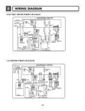
LIMIT THERMOSTAT GAS DRYER WIRING DIAGRAM POWER CORD L1 BLACK N WHITE GN/YL WHITE 1 WH1 TRANS BL2 3 1 ELECTRONIC CONTROL YL2 1 3 TAB RELAY BLACK BL3 123 NA6 6 5 4321 RED PINK ...-LIMIT THERMOSTAT WHITE DC VALVE1 DC VALVE2 MOISTURE THERMISTOR FLAME SENSOR DETECTOR CENTRIFUGAL SWITCH RED WHITE NC NO GRAY SAFETY THERMOSTAT 19 8 WIRING DIAGRAM ELECTRIC DRYER WIRING DIAGRAM L1 BLACK N WHITE L2 ELECTRONIC CONTROL 1 WH1 TRANS BL2 3 1 TAB RELAY TAB RELAY BLACK WHITE NA6 6 5 432 1 RED WHITE BACK BLUE ORANGE RED...
LIMIT THERMOSTAT GAS DRYER WIRING DIAGRAM POWER CORD L1 BLACK N WHITE GN/YL WHITE 1 WH1 TRANS BL2 3 1 ELECTRONIC CONTROL YL2 1 3 TAB RELAY BLACK BL3 123 NA6 6 5 4321 RED PINK ...-LIMIT THERMOSTAT WHITE DC VALVE1 DC VALVE2 MOISTURE THERMISTOR FLAME SENSOR DETECTOR CENTRIFUGAL SWITCH RED WHITE NC NO GRAY SAFETY THERMOSTAT 19 8 WIRING DIAGRAM ELECTRIC DRYER WIRING DIAGRAM L1 BLACK N WHITE L2 ELECTRONIC CONTROL 1 WH1 TRANS BL2 3 1 TAB RELAY TAB RELAY BLACK WHITE NA6 6 5 432 1 RED WHITE BACK BLUE ORANGE RED...
Service Manual
Page 22
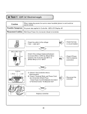
... properly connected. YES Check if the voltage measured between Connector BK2 or WH2- (Black Wire) Linked to Controller. (LED,LCD Display off) Measurement Condition With Dryer Power On; Connector linked to Controller. N (White) L (Black) L (Led) YES Check if the Controller wire is disconnected.
... properly connected. YES Check if the voltage measured between Connector BK2 or WH2- (Black Wire) Linked to Controller. (LED,LCD Display off) Measurement Condition With Dryer Power On; Connector linked to Controller. N (White) L (Black) L (Led) YES Check if the Controller wire is disconnected.
Service Manual
Page 23
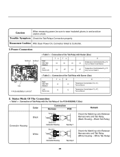
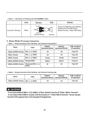
Measurement Condition With Dryer Power On; Status Mode Of The Connection < Table1 > : Connection of Tab Relay with Burner (Gas) High Mid High Medium Low Extra Low Ta B O O O O R Temperature Control ...
Measurement Condition With Dryer Power On; Status Mode Of The Connection < Table1 > : Connection of Tab Relay with Burner (Gas) High Mid High Medium Low Extra Low Ta B O O O O R Temperature Control ...
Service Manual
Page 24
... Tap relay 1 Remark Check the Matching color Between Harness wire and Tab Relay. (Black Housing - < Table 2 > : Connection of Connection". Because improper Connection of the equipment-dryer can be damaged of the Tab Relay and Connector Housing (Gas) Items Case Heater1 Heater2 Operation(black) operation(White) 1.Black and White Housing Wire , CROSS...
... Tap relay 1 Remark Check the Matching color Between Harness wire and Tab Relay. (Black Housing - < Table 2 > : Connection of Connection". Because improper Connection of the equipment-dryer can be damaged of the Tab Relay and Connector Housing (Gas) Items Case Heater1 Heater2 Operation(black) operation(White) 1.Black and White Housing Wire , CROSS...
Service Manual
Page 26
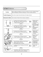
... Is resistance below 3Ω between Connector BL2- (Yellow wire) and BL2- (Brown wire)? Is resistance below 3Ω between Idler Switch terminals? Measurement Condition Turn the Dryer's Power Off, then measure resistance. 1 Idler Switch Lever Idler Switch Is resistance below 3Ω between Connector WH (White wire) and BL2- (Yellow wire)? YES (Not...
... Is resistance below 3Ω between Connector BL2- (Yellow wire) and BL2- (Brown wire)? Is resistance below 3Ω between Idler Switch terminals? Measurement Condition Turn the Dryer's Power Off, then measure resistance. 1 Idler Switch Lever Idler Switch Is resistance below 3Ω between Connector WH (White wire) and BL2- (Yellow wire)? YES (Not...
Service Manual
Page 27
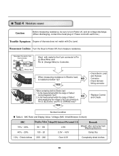
... wire)? Is the measurement within the range of Table 2 NO when measuring the voltage in Electric load, is resistance below 1Ω? Measurement Condition Turn the Dryer's Power Off, then measure resistance. Is the measurement within the range of Table 2 during Diagnostic Test? 2. Take 6pin Connector from Washing Machine Damp Dry 10...
... wire)? Is the measurement within the range of Table 2 NO when measuring the voltage in Electric load, is resistance below 1Ω? Measurement Condition Turn the Dryer's Power Off, then measure resistance. Is the measurement within the range of Table 2 during Diagnostic Test? 2. Take 6pin Connector from Washing Machine Damp Dry 10...
Service Manual
Page 28
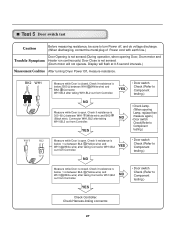
... Door, Drum motor and Trouble Symptom Heater run continuously) Door Close is not sensed. (Drum motor will flash at 0.5 second intervals.) Measurement Condition After turning Dryer Power Off, measure resistance. YES NO • Door switch Check (Refer to Component testing.) Measure while Door is closed . Check it resistance is below 1 Ω...
... Door, Drum motor and Trouble Symptom Heater run continuously) Door Close is not sensed. (Drum motor will flash at 0.5 second intervals.) Measurement Condition After turning Dryer Power Off, measure resistance. YES NO • Door switch Check (Refer to Component testing.) Measure while Door is closed . Check it resistance is below 1 Ω...


