
Service Manual
Page 2
... 3.2.3 PWB(PCB) ASSEMBLY, MAIN ...16 3.2.4 CAPACITOR...16 3.2.5 MICRO SWITCH ASSEMBLY ...16 3.2.6 COIL ASSEMBLY, SOLENOID ...17 3.2.7 CONTROL PANEL ...17 3.2.8 FAN AND MOTOR...18 3.2.9 DRAIN PAN ...18 3.3 REFRIGERATING CYCLE ...19 3.3.1 CONDENSER, EVAPORATOR AND CAPILLARY TUBE 19 3.3.2 ROTARY COMPRESSOR ...19 3.4 HOW TO REPLACE...
... 3.2.3 PWB(PCB) ASSEMBLY, MAIN ...16 3.2.4 CAPACITOR...16 3.2.5 MICRO SWITCH ASSEMBLY ...16 3.2.6 COIL ASSEMBLY, SOLENOID ...17 3.2.7 CONTROL PANEL ...17 3.2.8 FAN AND MOTOR...18 3.2.9 DRAIN PAN ...18 3.3 REFRIGERATING CYCLE ...19 3.3.1 CONDENSER, EVAPORATOR AND CAPILLARY TUBE 19 3.3.2 ROTARY COMPRESSOR ...19 3.4 HOW TO REPLACE...
Service Manual
Page 3
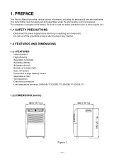
1. The refrigerant is charged at the factory. On/Off 2Hr. Be sure to read the safety precaution prior to servicing the unit. 1.1 SAFETY PRECAUTIONS • Disconnect the ...
1. The refrigerant is charged at the factory. On/Off 2Hr. Be sure to read the safety precaution prior to servicing the unit. 1.1 SAFETY PRECAUTIONS • Disconnect the ...
Service Manual
Page 4
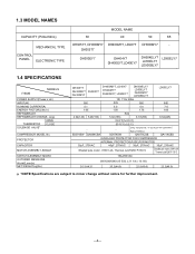
...POWER SUPPLY(Phase,V,Hz) INPUT(W) RUNNING CURRENT(A) ENERGY FACTOR(L/kw.h) REFRIGERANT REFRIGERANT CHARGE, oz(g) OPEN THERMISTOR CLOSE SOLENOID VALVE* COMPRESSOR MODEL No. PROTECTOR CAPACITOR MOTOR ASSEMBLY,SINGLE SWITCH ASSEMBLY,MICRO OUTSIDED MENSIONS WxHxD,mm(in) NET WEIGHT,kg(lbs) DH305Y7 DH300MY7 DH305T7 DH300EY7 DH400MY7, LD40Y7 DH404EY7 DH400EY7, LD40EY7 DH504ELY7 LD50ELY7 ... without notice for further improvement. -4- 1.3 MODEL NAMES CAPACITY (Pints/24hrs) MECHANICAL TYPE CONTROL PANEL ELECTRONIC TYPE MODEL NAME 30 40 50 65 DH305Y7, DH300MY7 DH400MY7,LD40Y7 DH500MY7 -
...POWER SUPPLY(Phase,V,Hz) INPUT(W) RUNNING CURRENT(A) ENERGY FACTOR(L/kw.h) REFRIGERANT REFRIGERANT CHARGE, oz(g) OPEN THERMISTOR CLOSE SOLENOID VALVE* COMPRESSOR MODEL No. PROTECTOR CAPACITOR MOTOR ASSEMBLY,SINGLE SWITCH ASSEMBLY,MICRO OUTSIDED MENSIONS WxHxD,mm(in) NET WEIGHT,kg(lbs) DH305Y7 DH300MY7 DH305T7 DH300EY7 DH400MY7, LD40Y7 DH404EY7 DH400EY7, LD40EY7 DH504ELY7 LD50ELY7 ... without notice for further improvement. -4- 1.3 MODEL NAMES CAPACITY (Pints/24hrs) MECHANICAL TYPE CONTROL PANEL ELECTRONIC TYPE MODEL NAME 30 40 50 65 DH305Y7, DH300MY7 DH400MY7,LD40Y7 DH500MY7 -

Service Manual
Page 6
..., to indicate bucket must be operated in the evaporator coil and the unit will not operate satisfactorily if the room temperature is drawn over a cold refrigerated dehumidifying coil. 1.6 HOW TO OPERATE DEHUMIDIFIER 1.6.1 HOW DOES THE DEHUMIDIFIER WORK? This warming effect further reduces the relative humidity of the surrounding air. 1.6.2 LOCATION FOR...
..., to indicate bucket must be operated in the evaporator coil and the unit will not operate satisfactorily if the room temperature is drawn over a cold refrigerated dehumidifying coil. 1.6 HOW TO OPERATE DEHUMIDIFIER 1.6.1 HOW DOES THE DEHUMIDIFIER WORK? This warming effect further reduces the relative humidity of the surrounding air. 1.6.2 LOCATION FOR...

Service Manual
Page 18
.... (See Figure 24) 5. Unfasten 3 screws that secure the shroud on the sides and then lift shroud from the base. (See Figure 25) -18- Discharge the refrigerant by hands carefully. 2. Unfasten 2 screws that secure the Motor and earth wire. (See Figure 23) 5. Turn the nut left and full out the Fan by...
.... (See Figure 24) 5. Unfasten 3 screws that secure the shroud on the sides and then lift shroud from the base. (See Figure 25) -18- Discharge the refrigerant by hands carefully. 2. Unfasten 2 screws that secure the Motor and earth wire. (See Figure 23) 5. Turn the nut left and full out the Fan by...

Service Manual
Page 19
.... 3. Remove the nuts and washers which fasten the compressor. (See Figure 29) 4. Pierce the pinch-off tube to discharge the refrigerant, using a refrigerant Recovery System. 2. Lift the H/E and open the H/E around 45 degree counterclockwise carefully. 5. Remove 4 screws between the housing assembly ... (See Figure 26) 4. Remove the compressor. (See Figure 29) Using Rotary Compressor models Figure 29 -19- After discharging the refrigerant completely, remove 2 screws between the condenser and evaporator. (See Figure 28) Figure 26 Figure 27 Figure 28 3.3.2 COMPRESSOR 1. After...
.... 3. Remove the nuts and washers which fasten the compressor. (See Figure 29) 4. Pierce the pinch-off tube to discharge the refrigerant, using a refrigerant Recovery System. 2. Lift the H/E and open the H/E around 45 degree counterclockwise carefully. 5. Remove 4 screws between the housing assembly ... (See Figure 26) 4. Remove the compressor. (See Figure 29) Using Rotary Compressor models Figure 29 -19- After discharging the refrigerant completely, remove 2 screws between the condenser and evaporator. (See Figure 28) Figure 26 Figure 27 Figure 28 3.3.2 COMPRESSOR 1. After...

Service Manual
Page 20
... counterclockwise. Evacuate as follows. 1) Connect the vacuum pump, as illustrated in the suction line through valves A and B to valve C by using a refrigerant recovery system. 2. CAUTION If high vacuum equipment is used, just crack valves A and B for 20 to the Lowside. A rise in pressure would... system is now pulling through the access valve which you installed as the system was opened. 2) Connect the charging cylinder as follows : 1) Refrigeration cycle systems are obtained. Use sil-fos solder and solder pinch-off tool. Valve B is still closed , stop the vacuum pump. 4) ...
... counterclockwise. Evacuate as follows. 1) Connect the vacuum pump, as illustrated in the suction line through valves A and B to valve C by using a refrigerant recovery system. 2. CAUTION If high vacuum equipment is used, just crack valves A and B for 20 to the Lowside. A rise in pressure would... system is now pulling through the access valve which you installed as the system was opened. 2) Connect the charging cylinder as follows : 1) Refrigeration cycle systems are obtained. Use sil-fos solder and solder pinch-off tool. Valve B is still closed , stop the vacuum pump. 4) ...

Service Manual
Page 23
... or replace. Compressor cycles on the Heat Exchange. Fan blade hits frame Internal compressor noise. Leak in electrical circuit Unit pressures not equalized Capacitor Wiring Refrigeration system Stuck compressor Overload protector (OLP) REMEDY If cracked, out of Motor Assembly The bucket is high, remove the OLP, cool, and retest.) -23- Adjust...
... or replace. Compressor cycles on the Heat Exchange. Fan blade hits frame Internal compressor noise. Leak in electrical circuit Unit pressures not equalized Capacitor Wiring Refrigeration system Stuck compressor Overload protector (OLP) REMEDY If cracked, out of Motor Assembly The bucket is high, remove the OLP, cool, and retest.) -23- Adjust...