

Owner's Manual
Page 4
...FROM MAINS Mains plug is , a single outlet circuit which powers only that you turn off this owner's manual to be connected to the same AC power outlet as being twisted, kinked, pinched, closed in fire ...conditions could result in a door, or walked upon a dedicated circuit; Check the specification page of the TV. 13 Do not allow an impact shock or any objects to telephone wires, lightening rods, or gas ...cables on the back of this unit by an authorized servicer. SAFETY INSTRUCTIONS 11 Never touch this product to plugs, wall outlets, and the point where the cord exits ...
...FROM MAINS Mains plug is , a single outlet circuit which powers only that you turn off this owner's manual to be connected to the same AC power outlet as being twisted, kinked, pinched, closed in fire ...conditions could result in a door, or walked upon a dedicated circuit; Check the specification page of the TV. 13 Do not allow an impact shock or any objects to telephone wires, lightening rods, or gas ...cables on the back of this unit by an authorized servicer. SAFETY INSTRUCTIONS 11 Never touch this product to plugs, wall outlets, and the point where the cord exits ...
Owner's Manual
Page 6
...- Add / Delete Channel (Manual Tuning 41 - User Mode 76 Picture Improvement Technology 77 Expert Picture Control 78 Picture Reset 80 Demo Mode 80 Image Sticking Minimization (ISM) Method 81 6 CONTENTS WARNING 2 SAFETY INSTRUCTIONS 3 FEATURE OF THIS TV 8 PREPARATION Accessories 9 Front... Panel Information 10 Back Panel Information 11 Stand Instruction 13 Cable Management 15 Desktop Pedestal Installation 16 Swivel Stand 16 VESA...
...- Add / Delete Channel (Manual Tuning 41 - User Mode 76 Picture Improvement Technology 77 Expert Picture Control 78 Picture Reset 80 Demo Mode 80 Image Sticking Minimization (ISM) Method 81 6 CONTENTS WARNING 2 SAFETY INSTRUCTIONS 3 FEATURE OF THIS TV 8 PREPARATION Accessories 9 Front... Panel Information 10 Back Panel Information 11 Stand Instruction 13 Cable Management 15 Desktop Pedestal Installation 16 Swivel Stand 16 VESA...

Owner's Manual
Page 17
... not use an LG brand wall mount when mounting the TV to the floor. NOTE G Screw length needed depends on their specifications. When attaching to the instructions included with the ... 50PV450C, 42/50PT250U, 50PV550U 60PV250, 60PV400, 60PV450, 60PV450C, 60PV550U 600 * 400 M8 4 PSW600B, PSW600BG ! CAUTION G Do not install your wall mount kit while your TV is turned on a solid wall perpendicular... to a wall. G When purchasing our wall mount kit, a detailed installation manual and all parts necessary for...
... not use an LG brand wall mount when mounting the TV to the floor. NOTE G Screw length needed depends on their specifications. When attaching to the instructions included with the ... 50PV450C, 42/50PT250U, 50PV550U 60PV250, 60PV400, 60PV450, 60PV450C, 60PV550U 600 * 400 M8 4 PSW600B, PSW600BG ! CAUTION G Do not install your wall mount kit while your TV is turned on a solid wall perpendicular... to a wall. G When purchasing our wall mount kit, a detailed installation manual and all parts necessary for...
Owner's Manual
Page 23
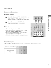
... and PR = red). 2 Connect the audio outputs of the DVD to use I Select the Component1 input source on the TV using the INPUT button on the TV. Y PB PR L R 1 2 2. I Turn on the TV. I Refer to the COMPONENT IN AUDIO 1 jacks on the DVD player, insert a DVD. Component ports on the... TV Y Y Video output ports Y on the TV. How to connect 1 Connect the video outputs (Y, PB, PR) of the DVD to the DVD player's manual for operating instructions. I If connected to the component input ports as shown below. ...
... and PR = red). 2 Connect the audio outputs of the DVD to use I Select the Component1 input source on the TV using the INPUT button on the TV. Y PB PR L R 1 2 2. I Turn on the TV. I Refer to the COMPONENT IN AUDIO 1 jacks on the DVD player, insert a DVD. Component ports on the... TV Y Y Video output ports Y on the TV. How to connect 1 Connect the video outputs (Y, PB, PR) of the DVD to the DVD player's manual for operating instructions. I If connected to the component input ports as shown below. ...
Owner's Manual
Page 24
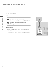
How to use I Refer to the HDMI/DVI IN 1, 2, or HDMI IN 3 jack on the remote control. HDMI-DTV OUTPUT 1 OPTICAL DIGITAL AUDIO AUDIO OUT (RGB/DV 2 1 HDMI/DVI IN RS-232C IN (CONTROL & SERVICE) RGB IN(PC) 24 I Select the HDMI1, 2, or 3 input source on the TV using the INPUT button on the TV. 2 No separate audio connection is necessary. EXTERNAL EQUIPMENT SETUP EXTERNAL EQUIPMENT SETUP HDMI Connection 1. HDMI supports both audio and video. 2. How to connect 1 Connect the HDMI output of the DVD to the DVD player's manual for operating instructions.
How to use I Refer to the HDMI/DVI IN 1, 2, or HDMI IN 3 jack on the remote control. HDMI-DTV OUTPUT 1 OPTICAL DIGITAL AUDIO AUDIO OUT (RGB/DV 2 1 HDMI/DVI IN RS-232C IN (CONTROL & SERVICE) RGB IN(PC) 24 I Select the HDMI1, 2, or 3 input source on the TV using the INPUT button on the TV. 2 No separate audio connection is necessary. EXTERNAL EQUIPMENT SETUP EXTERNAL EQUIPMENT SETUP HDMI Connection 1. HDMI supports both audio and video. 2. How to connect 1 Connect the HDMI output of the DVD to the DVD player's manual for operating instructions.
Owner's Manual
Page 27
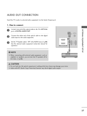
...the optical output port. G Audio with external audio equipment, such as amplifiers or speakers, you can turn the TV speakers off in the AUDIO menu. (G p.88) See the external audio equipment instruction manual for operation. OPTICAL DIGITAL AUDIO OUT AUDIO (RGB/DVI) RS-232C IN RGB(PC) 1 2 1 HDMI/DVI... IN ! How to connect 1 Connect one end of the optical cable to the TV's OPTICAL port of DIGITAL AUDIO OUT. 2 Connect the...
...the optical output port. G Audio with external audio equipment, such as amplifiers or speakers, you can turn the TV speakers off in the AUDIO menu. (G p.88) See the external audio equipment instruction manual for operation. OPTICAL DIGITAL AUDIO OUT AUDIO (RGB/DVI) RS-232C IN RGB(PC) 1 2 1 HDMI/DVI... IN ! How to connect 1 Connect one end of the optical cable to the TV's OPTICAL port of DIGITAL AUDIO OUT. 2 Connect the...


