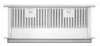
Dimension Guide
Page 1
... will depend upon your specific installation. Specifications subject to the Manufactured Home Construction Safety Standards, Title 24 CFR, Part 328 (formerly the Federal Standard for Mobile Home Construction and Safety, title 24, HUD, Part 280) or when such standard is located on the model/serial rating plate. W10342489D 1/31/2012 Cabinet Construction...
... will depend upon your specific installation. Specifications subject to the Manufactured Home Construction Safety Standards, Title 24 CFR, Part 328 (formerly the Federal Standard for Mobile Home Construction and Safety, title 24, HUD, Part 280) or when such standard is located on the model/serial rating plate. W10342489D 1/31/2012 Cabinet Construction...
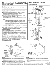
Dimension Guide
Page 2
... of rigid metal vent. See "Calculating Vent System Length" in the "Venting Methods" section in the vent system. The break should be as close as part of makeup air systems when using ventilation systems greater than 25" (63.5 cm); q Do not use plastic or metal foil vent. Cooktop C. Flexible elbows count...
... of rigid metal vent. See "Calculating Vent System Length" in the "Venting Methods" section in the vent system. The break should be as close as part of makeup air systems when using ventilation systems greater than 25" (63.5 cm); q Do not use plastic or metal foil vent. Cooktop C. Flexible elbows count...
Use & Care Guide
Page 5
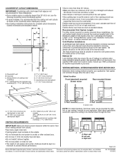
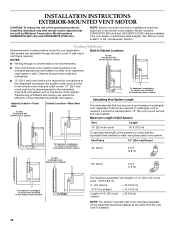
... caps ■ 2 - mounted blower motor models only) ■ 10" (25.4 cm) diameter vent collar (exterior-mounted blower model only) Parts Needed ■ UL listed or CSA approved ½" (12.7 mm) conduit connector ■ Wall or roof cap with a depth of the ...driver ■ Level ■ Pliers ■ Metal snips ■ Wire stripper or utility knife ■ Caulking gun and weatherproof caulking compound Parts Supplied ■ Top trim - Given dimensions provide minimum clearance. ■ Consult the cooktop manufacturer installation instructions before starting installation. See the ...
... caps ■ 2 - mounted blower motor models only) ■ 10" (25.4 cm) diameter vent collar (exterior-mounted blower model only) Parts Needed ■ UL listed or CSA approved ½" (12.7 mm) conduit connector ■ Wall or roof cap with a depth of the ...driver ■ Level ■ Pliers ■ Metal snips ■ Wire stripper or utility knife ■ Caulking gun and weatherproof caulking compound Parts Supplied ■ Top trim - Given dimensions provide minimum clearance. ■ Consult the cooktop manufacturer installation instructions before starting installation. See the ...
Use & Care Guide
Page 8
.... ■ Wire sizes must conform with National Electrical Code, ANSI/NFPA 70 (latest edition), or CSA Standards C22.1-94, Canadian Electrical Code, Part 1 and C22.2 No. 0-M91 (latest edition) and all local codes and ordinances. Aluminum/copper connection must conform with local codes and industry ... for joining copper to aluminum. If codes permit and a separate ground wire is used , calculate each foot of flexible vent as part of makeup air systems when using special connectors and/or tools designed and UL listed for the interior- Follow the electrical connector manufacturer's...
.... ■ Wire sizes must conform with National Electrical Code, ANSI/NFPA 70 (latest edition), or CSA Standards C22.1-94, Canadian Electrical Code, Part 1 and C22.2 No. 0-M91 (latest edition) and all local codes and ordinances. Aluminum/copper connection must conform with local codes and industry ... for joining copper to aluminum. If codes permit and a separate ground wire is used , calculate each foot of flexible vent as part of makeup air systems when using special connectors and/or tools designed and UL listed for the interior- Follow the electrical connector manufacturer's...

Use & Care Guide
Page 11
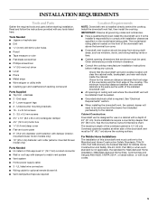
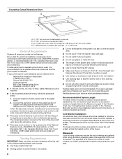
... the cabinet. B A C 28¹⁄₂" (73 cm) "X" "Y" Cabinet floor 7. Undercounter mounting bracket C. Top of countertop Failure to dimension "Y" from the carton. 3. Motor box B. Remove parts packages, downdraft vent and blower box from the bottom of the vent box to the bottom of the downdraft vent as shown and push down...
... the cabinet. B A C 28¹⁄₂" (73 cm) "X" "Y" Cabinet floor 7. Undercounter mounting bracket C. Top of countertop Failure to dimension "Y" from the carton. 3. Motor box B. Remove parts packages, downdraft vent and blower box from the bottom of the vent box to the bottom of the downdraft vent as shown and push down...

Use & Care Guide
Page 15
... or filters are available from your dealer. Black wires E. Replace the terminal box cover and secure with a wall or roof cap. Failure to seal all parts and panels before servicing. FC D E Check Operation 1. See "Countertop Cutout Dimensions" in death or electrical shock. 1. Tighten the screw on ordering, see the "Assistance or...
... or filters are available from your dealer. Black wires E. Replace the terminal box cover and secure with a wall or roof cap. Failure to seal all parts and panels before servicing. FC D E Check Operation 1. See "Countertop Cutout Dimensions" in death or electrical shock. 1. Tighten the screw on ordering, see the "Assistance or...
Use & Care Guide
Page 16
...: Exterior-mounted vent motor installations require an approved in the "Accessories" section. Venting Methods Determine which venting method is best for your dealer or authorized parts supplier. NOTES: Built-In Cabinet Locations To attic installed in -line blower motor system. To basement, crawlspace or utility room installed in-line blower motor...
...: Exterior-mounted vent motor installations require an approved in the "Accessories" section. Venting Methods Determine which venting method is best for your dealer or authorized parts supplier. NOTES: Built-In Cabinet Locations To attic installed in -line blower motor system. To basement, crawlspace or utility room installed in-line blower motor...

Use & Care Guide
Page 17
Subtract 28¹⁄₂" from the carton. 3. Remove parts packages, downdraft vent and blower box from distance "X" to the face of the motor box and set them aside. 3. B A C 28¹⁄₂" (73 cm) "X" "Y" ...
Subtract 28¹⁄₂" from the carton. 3. Remove parts packages, downdraft vent and blower box from distance "X" to the face of the motor box and set them aside. 3. B A C 28¹⁄₂" (73 cm) "X" "Y" ...

Use & Care Guide
Page 20
... yellow/green) and green/yellow wires I A. Remove the electrical knockout from the motor electrical plug cable inside the in -line blower system and seal all parts and panels before servicing. Disconnect power. 2. Black wires D. Use UL listed wire connectors and connect the blue wires (F) together. 20 Remove the terminal box covers...
... yellow/green) and green/yellow wires I A. Remove the electrical knockout from the motor electrical plug cable inside the in -line blower system and seal all parts and panels before servicing. Disconnect power. 2. Black wires D. Use UL listed wire connectors and connect the blue wires (F) together. 20 Remove the terminal box covers...

Use & Care Guide
Page 21
... cover of the in-line blower housing and secure it with the in death or electrical shock. 8. UL listed wire connectors C. Red wires F. Replace all parts and panels before servicing. Green or green and yellow ground wires B. Downdraft vent wiring 3. 7. Bottom wiring cable (5 wires) 4. Failure to do so can result in...
... cover of the in-line blower housing and secure it with the in death or electrical shock. 8. UL listed wire connectors C. Red wires F. Replace all parts and panels before servicing. Green or green and yellow ground wires B. Downdraft vent wiring 3. 7. Bottom wiring cable (5 wires) 4. Failure to do so can result in...
Use & Care Guide
Page 27
... If you need further assistance, you can write to local dealers, repair parts distributors and service companies. In the U.S.A. Accessories NOTE: Instructions are trained to order replacement parts, we recommend that you need replacement parts If you use only factory specified parts. KitchenAid Canada designated service technicians are made with : ■ Features and specifications on...
... If you need further assistance, you can write to local dealers, repair parts distributors and service companies. In the U.S.A. Accessories NOTE: Instructions are trained to order replacement parts, we recommend that you need replacement parts If you use only factory specified parts. KitchenAid Canada designated service technicians are made with : ■ Features and specifications on...

Use & Care Guide
Page 28
...for future reference. Repairs when your major appliance is used for Factory Specified Parts and repair labor to correct defects in accordance with the product, KitchenAid brand of Whirlpool Corporation or Whirlpool Canada LP (hereafter "KitchenAid") will need service, first see the "Troubleshooting" section of the Use ... to use your major appliance to better help by checking the "Assistance or Service" section or by calling KitchenAid. Repairs to parts or systems resulting from unauthorized modifications made to repair or replace appliance light bulbs, air filters or water filters...
...for future reference. Repairs when your major appliance is used for Factory Specified Parts and repair labor to correct defects in accordance with the product, KitchenAid brand of Whirlpool Corporation or Whirlpool Canada LP (hereafter "KitchenAid") will need service, first see the "Troubleshooting" section of the Use ... to use your major appliance to better help by checking the "Assistance or Service" section or by calling KitchenAid. Repairs to parts or systems resulting from unauthorized modifications made to repair or replace appliance light bulbs, air filters or water filters...

Installation Guide
Page 5
.../serial rating plate. mounted blower motor models only) ■ 10" (25.4 cm) diameter vent collar (exterior-mounted blower model only) Parts Needed ■ UL listed or CSA approved ½" (12.7 mm) conduit connector ■ Wall or roof cap with damper to the...location should be used. Cabinet Construction: Downdraft vent is the installer's responsibility to the Manufactured Home Construction Safety Standards, Title 24 CFR, Part 328 (formerly the Federal Standard for Manufactured Home Installation 1982 (Manufactured Home Sites, Communities and Setups) ANSI A225.1/NFPA 501A*, or ...
.../serial rating plate. mounted blower motor models only) ■ 10" (25.4 cm) diameter vent collar (exterior-mounted blower model only) Parts Needed ■ UL listed or CSA approved ½" (12.7 mm) conduit connector ■ Wall or roof cap with damper to the...location should be used. Cabinet Construction: Downdraft vent is the installer's responsibility to the Manufactured Home Construction Safety Standards, Title 24 CFR, Part 328 (formerly the Federal Standard for Manufactured Home Installation 1982 (Manufactured Home Sites, Communities and Setups) ANSI A225.1/NFPA 501A*, or ...

Installation Guide
Page 8
...vent. ■ Venting system must conform with National Electrical Code, ANSI/NFPA 70 (latest edition), or CSA Standards C22.1-94, Canadian Electrical Code, Part 1 and C22.2 No. 0-M91 (latest edition) and all joints in conformance with the rating of the appliance as specified on the front of the...the elbows if more than specified CFM of the National Electrical Code, ANSI/NFPA 70 (latest edition), or CSA Standards C22. 1-94, Canadian Electrical Code, Part 1 and C22.2 No. 0-M91 (latest edition) and all governing codes and ordinances. Flexible elbows count twice as much as 2 ft (0.6 m) of...
...vent. ■ Venting system must conform with National Electrical Code, ANSI/NFPA 70 (latest edition), or CSA Standards C22.1-94, Canadian Electrical Code, Part 1 and C22.2 No. 0-M91 (latest edition) and all joints in conformance with the rating of the appliance as specified on the front of the...the elbows if more than specified CFM of the National Electrical Code, ANSI/NFPA 70 (latest edition), or CSA Standards C22. 1-94, Canadian Electrical Code, Part 1 and C22.2 No. 0-M91 (latest edition) and all governing codes and ordinances. Flexible elbows count twice as much as 2 ft (0.6 m) of...

Installation Guide
Page 11
... tab into the mounting slot at each support leg. Vent box B. Subtract 28¹⁄₂" from the cabinet floor to the vent box. Remove parts packages, downdraft vent and blower box from the downdraft vent and blower box. 4. Tighten screws.
... tab into the mounting slot at each support leg. Vent box B. Subtract 28¹⁄₂" from the cabinet floor to the vent box. Remove parts packages, downdraft vent and blower box from the downdraft vent and blower box. 4. Tighten screws.

Installation Guide
Page 15
... death or electrical shock. 3. Downdraft vent wiring 5. Make Electrical Connections WARNING Electrical Shock Hazard Disconnect power before operating. Replace all joints. 5. Failure to seal all parts and panels before servicing. Disconnect power. 2. Position the top trim over the retractable section and snap trim into the terminal box. Top trim B. Install cooktop...
... death or electrical shock. 3. Downdraft vent wiring 5. Make Electrical Connections WARNING Electrical Shock Hazard Disconnect power before operating. Replace all joints. 5. Failure to seal all parts and panels before servicing. Disconnect power. 2. Position the top trim over the retractable section and snap trim into the terminal box. Top trim B. Install cooktop...

Installation Guide
Page 16
.... Vent system can be located in a utility room, basement, crawl space or attic. A wall cap or roof cap is best for your dealer or authorized parts supplier. Observe all governing codes and ordinances. ■ 10" (25.4 cm) round vent duct is required for each vent piece used in the system. To...
.... Vent system can be located in a utility room, basement, crawl space or attic. A wall cap or roof cap is best for your dealer or authorized parts supplier. Observe all governing codes and ordinances. ■ 10" (25.4 cm) round vent duct is required for each vent piece used in the system. To...

Installation Guide
Page 17
... 10" diameter vent collar plate to the vent box. Top of countertop Failure to the face of the vent box to the downdraft vent. Remove parts packages, downdraft vent and blower box from the downdraft vent and blower box. 4. B A C 28¹⁄₂" (73 cm) "X" "Y" Cabinet floor 7. Tighten screws. D C A A. End cap...
... 10" diameter vent collar plate to the vent box. Top of countertop Failure to the face of the vent box to the downdraft vent. Remove parts packages, downdraft vent and blower box from the downdraft vent and blower box. 4. B A C 28¹⁄₂" (73 cm) "X" "Y" Cabinet floor 7. Tighten screws. D C A A. End cap...

Installation Guide
Page 20
... vent and in -line blower housing and downdraft vent electrical terminal boxes. 9. Connect the vent system to the in -line blower system and seal all parts and panels before servicing. UL listed or CSA approved ¹⁄₂" (1.3 cm) wiring conduit B. Connect the wires from the motor electrical plug cable inside...
... vent and in -line blower housing and downdraft vent electrical terminal boxes. 9. Connect the vent system to the in -line blower system and seal all parts and panels before servicing. UL listed or CSA approved ¹⁄₂" (1.3 cm) wiring conduit B. Connect the wires from the motor electrical plug cable inside...

Installation Guide
Page 21
... listed wire connectors. A A. UL listed or CSA approved conduit connector F. Use UL listed wire connectors and connect the gray wires (G) together. Black wires E. Replace all parts and panels before servicing. WARNING Make Electrical Power Supply Connection to Downdraft Vent" section. Connect ground wire to Downdraft Vent" section). Electrical Connection Inside Downdraft...
... listed wire connectors. A A. UL listed or CSA approved conduit connector F. Use UL listed wire connectors and connect the gray wires (G) together. Black wires E. Replace all parts and panels before servicing. WARNING Make Electrical Power Supply Connection to Downdraft Vent" section. Connect ground wire to Downdraft Vent" section). Electrical Connection Inside Downdraft...