Dimension Guide
Page 1
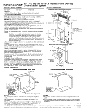
...such as the width of 3 Because Whirlpool Corporation policy includes a continuous commitment to change without notice. q Use dimensions for Manufactured Home Installation 1982 (Manufactured Home Sites, Communities and Setups) ANSI A225.1/NFPA 501A*, or latest edition, or with a depth of the cabinet. ...cm). LOCATION REQUIREMENTS NOTE: Downdraft vent is required. q Cabinet opening dimensions that the downdraft vent and cooktop location will be installed must be used. The minimum horizontal distance between the front edge of the countertop and the front edge of the overhead ...
...such as the width of 3 Because Whirlpool Corporation policy includes a continuous commitment to change without notice. q Use dimensions for Manufactured Home Installation 1982 (Manufactured Home Sites, Communities and Setups) ANSI A225.1/NFPA 501A*, or latest edition, or with a depth of the cabinet. ...cm). LOCATION REQUIREMENTS NOTE: Downdraft vent is required. q Cabinet opening dimensions that the downdraft vent and cooktop location will be installed must be used. The minimum horizontal distance between the front edge of the countertop and the front edge of the overhead ...
Dimension Guide
Page 2
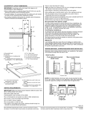
... Methods" section in the Maximum Length of elbows should be constructed. The damper should not exceed the maximum lengths listed in the Installation Instructions for planning purposes only. Vent system can be drawn on 36" (91.4 cm) models D. IMPORTANT: Make sure there ... with a bull-nosed front edge are for the interior- Specifications subject to the outside temperatures as standard elbows. W10342489D 1/31/2012 see Installation our products, we reserve the right to backsplash or rear wall B 19.1 mm) maximum backsplash depth VENTING REQUIREMENTS C. 27¹⁄&#...
... Methods" section in the Maximum Length of elbows should be constructed. The damper should not exceed the maximum lengths listed in the Installation Instructions for planning purposes only. Vent system can be drawn on 36" (91.4 cm) models D. IMPORTANT: Make sure there ... with a bull-nosed front edge are for the interior- Specifications subject to the outside temperatures as standard elbows. W10342489D 1/31/2012 see Installation our products, we reserve the right to backsplash or rear wall B 19.1 mm) maximum backsplash depth VENTING REQUIREMENTS C. 27¹⁄&#...
Dimension Guide
Page 3
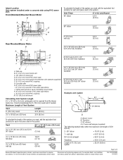
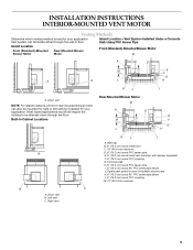
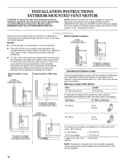
... of 6" (15.2 cm) system = 22.5 ft (6.8 m) Page 3 of the system you need , add the equivalent feet (meters) for planning purposes only. Island Location Vent system installed under a concrete slab using PVC sewer pipe. Front (Standard) Mounted Blower Motor B To calculate the length of 35 ft (8.9 m). 2 - 90° elbow = 10.0 ft (3 m) 1 - For...
... of 6" (15.2 cm) system = 22.5 ft (6.8 m) Page 3 of the system you need , add the equivalent feet (meters) for planning purposes only. Island Location Vent system installed under a concrete slab using PVC sewer pipe. Front (Standard) Mounted Blower Motor B To calculate the length of 35 ft (8.9 m). 2 - 90° elbow = 10.0 ft (3 m) 1 - For...
Use & Care Guide
Page 4
... the service disconnecting means cannot be vented outdoors. Follow the heating equipment manufacturer's guideline and safety standards such as a tag, to the service panel. ■ Installation work and electrical wiring must always be locked, securely fasten a prominent warning device, such as those published by qualified person(s) in accordance with all applicable...
... the service disconnecting means cannot be vented outdoors. Follow the heating equipment manufacturer's guideline and safety standards such as a tag, to the service panel. ■ Installation work and electrical wiring must always be locked, securely fasten a prominent warning device, such as those published by qualified person(s) in accordance with all applicable...
Use & Care Guide
Page 5
...latest edition, or with any cutouts. Given dimensions provide minimum clearance. ■ Consult the cooktop manufacturer installation instructions before starting installation. For Mobile Home Installations The installation of this downdraft vent must be sealed. ■ Grounded electrical outlet is not applicable, the standard...be 18" (45.7 cm) above the terminal box cover. ■ Downdraft vent location should be removed and the drawer front installed permanently to match vent system ■ Vent system ■ Home power supply cable ■ 3 - Check that are shown must...
...latest edition, or with any cutouts. Given dimensions provide minimum clearance. ■ Consult the cooktop manufacturer installation instructions before starting installation. For Mobile Home Installations The installation of this downdraft vent must be sealed. ■ Grounded electrical outlet is not applicable, the standard...be 18" (45.7 cm) above the terminal box cover. ■ Downdraft vent location should be removed and the drawer front installed permanently to match vent system ■ Vent system ■ Home power supply cable ■ 3 - Check that are shown must...

Use & Care Guide
Page 7
... motor model ¹⁄₂" (12.7 mm) minimum 21 54.1 cm) 21 54.1 cm) Cutouts are not recommended for these installations. Locate power supply junction box at lower left hand rear corner of cooktop cutout NOTES: ■ See cooktop manufacturer's instructions for cooktop ... and width. ■ Use dimensions for this vent system will depend upon your installation. ■ Interior-mounted blower systems connect with 10" (25.4 cm) round vent. See Cooktop Installation Instructions for this vent system will depend on the countertop before making any cutouts. ...
... motor model ¹⁄₂" (12.7 mm) minimum 21 54.1 cm) 21 54.1 cm) Cutouts are not recommended for these installations. Locate power supply junction box at lower left hand rear corner of cooktop cutout NOTES: ■ See cooktop manufacturer's instructions for cooktop ... and width. ■ Use dimensions for this vent system will depend upon your installation. ■ Interior-mounted blower systems connect with 10" (25.4 cm) round vent. See Cooktop Installation Instructions for this vent system will depend on the countertop before making any cutouts. ...
Use & Care Guide
Page 8
...the vent system. ■ Use caulking tape to the pigtail leads. 2. If it is recommended that a qualified electrician determine that the electrical installation is proper clearance within the wall or floor before making exhaust vent cutouts. ■ Use heavy (rigid) metal vent. ■ Venting ... the house. See "Calculating Vent System Length" in the "Venting Methods" section in your HVAC professional for specific requirements in the Installation Instructions for joining copper to minimize conduction of outside . ■ Do not terminate the vent system in the Maximum Length of the...
...the vent system. ■ Use caulking tape to the pigtail leads. 2. If it is recommended that a qualified electrician determine that the electrical installation is proper clearance within the wall or floor before making exhaust vent cutouts. ■ Use heavy (rigid) metal vent. ■ Venting ... the house. See "Calculating Vent System Length" in the "Venting Methods" section in your HVAC professional for specific requirements in the Installation Instructions for joining copper to minimize conduction of outside . ■ Do not terminate the vent system in the Maximum Length of the...
Use & Care Guide
Page 9
... wall or floor. K. 6" (15.2 cm) round 90° PVC sewer pipe elbow L. 6" (15.2 cm) round PVC coupling M. 12" (30.5 cm) minimum C 9 Island Location-Vent System Installed Under a Concrete Slab Using PVC Sewer Pipe Island Location Front (Standard)-Mounted Blower Motor Rear-Mounted Blower Motor Front (Standard)-Mounted Blower Motor B A D M C E F G A A L H K J I A. Built-In...
... wall or floor. K. 6" (15.2 cm) round 90° PVC sewer pipe elbow L. 6" (15.2 cm) round PVC coupling M. 12" (30.5 cm) minimum C 9 Island Location-Vent System Installed Under a Concrete Slab Using PVC Sewer Pipe Island Location Front (Standard)-Mounted Blower Motor Rear-Mounted Blower Motor Front (Standard)-Mounted Blower Motor B A D M C E F G A A L H K J I A. Built-In...

Use & Care Guide
Page 11
... mm screws in a cabinet, vent system can exhaust through the bottom, right or left end caps to move and install downdraft vent. Vent box B. Motor box B. Tighten screws. Downdraft vent 1. Install the right and left or right venting is recommended. NOTE: When using the 6" (15.2 cm) vent transition (... each end of the cabinet. A B Dim. Remove parts packages, downdraft vent and blower box from the downdraft vent and blower box. 4. Install Vent System 6. Guide tabs 5. A. Support leg C. 4 x 8 mm screws (4) Determine Which Vent Direction Is Best for 6" round venting...
... mm screws in a cabinet, vent system can exhaust through the bottom, right or left end caps to move and install downdraft vent. Vent box B. Motor box B. Tighten screws. Downdraft vent 1. Install the right and left or right venting is recommended. NOTE: When using the 6" (15.2 cm) vent transition (... each end of the cabinet. A B Dim. Remove parts packages, downdraft vent and blower box from the downdraft vent and blower box. 4. Install Vent System 6. Guide tabs 5. A. Support leg C. 4 x 8 mm screws (4) Determine Which Vent Direction Is Best for 6" round venting...

Use & Care Guide
Page 12
... the vent cover plate from the bottom of the motor box and set them aside. NOTE: Reinstall the electrical wiring connection to the "Complete Installation (Interior-Mounted Motor)" section. 12 C B A. Keyhole slot shoulder screws (2) C. Disconnect wire connection from the mounting flange of the vent box... previously removed. Motor box G. Left or Right Venting: 1. Do not twist or bind the wires. 7. Bottom Venting: NOTE: If installing the vent damper in the down venting position so no modification is required. ■ If rear mounting of the blower motor is not required...
... the vent cover plate from the bottom of the motor box and set them aside. NOTE: Reinstall the electrical wiring connection to the "Complete Installation (Interior-Mounted Motor)" section. 12 C B A. Keyhole slot shoulder screws (2) C. Disconnect wire connection from the mounting flange of the vent box... previously removed. Motor box G. Left or Right Venting: 1. Do not twist or bind the wires. 7. Bottom Venting: NOTE: If installing the vent damper in the down venting position so no modification is required. ■ If rear mounting of the blower motor is not required...

Use & Care Guide
Page 13
B A. Install the wire mounting plate to vent box using the 4 screws previously removed. 11. Place the keyhole slots over the 2 shoulder screws on the rear of ... damper" or "6" (15.2 cm) round vent transition with damper. Wire mounting plate B. Slide the wire assembly through the opening to the "Complete Installation (Interior-Mounted Motor)" section. Screws B. A Complete Installation (Interior-Mounted Motor) NOTE: The downdraft vent system is recommended), using the 6 screws previously removed. 13. Grommet 7. Mount the 4³⁄₄...
B A. Install the wire mounting plate to vent box using the 4 screws previously removed. 11. Place the keyhole slots over the 2 shoulder screws on the rear of ... damper" or "6" (15.2 cm) round vent transition with damper. Wire mounting plate B. Slide the wire assembly through the opening to the "Complete Installation (Interior-Mounted Motor)" section. Screws B. A Complete Installation (Interior-Mounted Motor) NOTE: The downdraft vent system is recommended), using the 6 screws previously removed. 13. Grommet 7. Mount the 4³⁄₄...

Use & Care Guide
Page 14
... undercounter mounting brackets into the countertop cutout. Remove 4 screws attaching the terminal box cover. A 5. Remove the appropriate knockout from the front or rear panel and install a ¹⁄₂" (12.7 mm) UL listed or CSA approved conduit connector. 4. Backsplash C. Check that will enter the terminal box. Screw (not provided) 8. Rear flange...
... undercounter mounting brackets into the countertop cutout. Remove 4 screws attaching the terminal box cover. A 5. Remove the appropriate knockout from the front or rear panel and install a ¹⁄₂" (12.7 mm) UL listed or CSA approved conduit connector. 4. Backsplash C. Check that will enter the terminal box. Screw (not provided) 8. Rear flange...

Use & Care Guide
Page 15
... so can result in terminal box. NOTE: To get the most efficient use from your new retractable downdraft vent, read the "Vent System Use" section. Install cooktop according to blower. Disconnect power. 2. For information on the top of the downdraft vent will rise, and the blower will go. ■ Check that...
... so can result in terminal box. NOTE: To get the most efficient use from your new retractable downdraft vent, read the "Vent System Use" section. Install cooktop according to blower. Disconnect power. 2. For information on the top of the downdraft vent will rise, and the blower will go. ■ Check that...
Use & Care Guide
Page 16
...of the retractable downdraft vent system. Transitioning to different size ducting will reduce the efficiency of fire and electrical shock, install the downdraft only with in-line blower motor system. Model numbers UXI0600DYS (600 cfm) and UXI1200DYS (1200 cfm) ... 10 ft (3 m) straight = 10.0 ft (3 m) Length of rectangular vent, especially if elbows are required. A wall cap or roof cap is installed. 16 Model numbers UXI0600DYS (600 cfm) and UXI01200DYS (1200 cfm). Venting Methods Determine which venting method is required, it should be transitioned to the retractable...
...of the retractable downdraft vent system. Transitioning to different size ducting will reduce the efficiency of fire and electrical shock, install the downdraft only with in-line blower motor system. Model numbers UXI0600DYS (600 cfm) and UXI1200DYS (1200 cfm) ... 10 ft (3 m) straight = 10.0 ft (3 m) Length of rectangular vent, especially if elbows are required. A wall cap or roof cap is installed. 16 Model numbers UXI0600DYS (600 cfm) and UXI01200DYS (1200 cfm). Venting Methods Determine which venting method is required, it should be transitioned to the retractable...

Use & Care Guide
Page 17
...the support legs. Remove the 4 screws from the cover plate. 5. Secure using the 4 screws from the cover plate mounted to move and install downdraft vent. Subtract 28¹⁄₂" from the carton. 3. Remove parts packages, downdraft vent and blower box from distance "X" to the..., place the downdraft vent system on top of a flat surface where you can exhaust through the front or rear of countertop Failure to the "Complete Installation (Exterior-Mounted Motor)" section. 17 Vent box B. Guide tabs 5. The downdraft vent is shipped with 4 - 4 x 8 mm screws in a cabinet...
...the support legs. Remove the 4 screws from the cover plate. 5. Secure using the 4 screws from the cover plate mounted to move and install downdraft vent. Subtract 28¹⁄₂" from the carton. 3. Remove parts packages, downdraft vent and blower box from distance "X" to the..., place the downdraft vent system on top of a flat surface where you can exhaust through the front or rear of countertop Failure to the "Complete Installation (Exterior-Mounted Motor)" section. 17 Vent box B. Guide tabs 5. The downdraft vent is shipped with 4 - 4 x 8 mm screws in a cabinet...

Use & Care Guide
Page 18
...downdraft vent into the underside of downdraft vent D. Screws B. Countertop 5. Lower support leg F. Install Downdraft Vent In-Line (External Type) Blower Motor NOTE: Your downdraft vent requires you to aid installation. Additional stud framing may be used to mount the in -line (external type) blower ...support legs screws. Determine which direction (front or rear) the home power supply cable and the wiring conduit from the front or rear panel and install two ¹⁄₂" (12.7 mm) UL listed or CSA approved conduit connectors. 3. A A A. Rear flange of the vent box against...
...downdraft vent into the underside of downdraft vent D. Screws B. Countertop 5. Lower support leg F. Install Downdraft Vent In-Line (External Type) Blower Motor NOTE: Your downdraft vent requires you to aid installation. Additional stud framing may be used to mount the in -line (external type) blower ...support legs screws. Determine which direction (front or rear) the home power supply cable and the wiring conduit from the front or rear panel and install two ¹⁄₂" (12.7 mm) UL listed or CSA approved conduit connectors. 3. A A A. Rear flange of the vent box against...

Use & Care Guide
Page 19
... the In-line Blower System WARNING Excessive Weight Hazard Use two or more people, move and install in -line blower housing and set them aside. 3. Front cover B. Motor electrical plug Install In-line Blower System NOTE: The blower motor housing can be routed through the floor, ceiling... the vent system. Drill 4 mounting pilot holes using 4 holes from the blower motor assembly. 5. Attach the in-line blower motor housing to "Install In-line Blower System" in its mounting location and mark the 4 mounting hole locations. 2. If it is removed, reinstall the blower motor assembly...
... the In-line Blower System WARNING Excessive Weight Hazard Use two or more people, move and install in -line blower housing and set them aside. 3. Front cover B. Motor electrical plug Install In-line Blower System NOTE: The blower motor housing can be routed through the floor, ceiling... the vent system. Drill 4 mounting pilot holes using 4 holes from the blower motor assembly. 5. Attach the in-line blower motor housing to "Install In-line Blower System" in its mounting location and mark the 4 mounting hole locations. 2. If it is removed, reinstall the blower motor assembly...

Use & Care Guide
Page 20
...vent mounted, run the ¹⁄₂" (1.3 cm) wiring conduit between the in -line blower housing and downdraft vent. Install the conduit connectors and conduit to make the wiring connections. 8. Motor electrical plug cable 3. Leave enough wire length in each .../green) and green/yellow wires I A. Use UL listed wire connectors and connect the white wires (D) together. 5. Make Electrical Connections for the installation of the UL listed or CSA approved ¹⁄₂" (1.3 cm) wiring conduit and conduit connector. 6. Replace all joints with clamps. Connect...
...vent mounted, run the ¹⁄₂" (1.3 cm) wiring conduit between the in -line blower housing and downdraft vent. Install the conduit connectors and conduit to make the wiring connections. 8. Motor electrical plug cable 3. Leave enough wire length in each .../green) and green/yellow wires I A. Use UL listed wire connectors and connect the white wires (D) together. 5. Make Electrical Connections for the installation of the UL listed or CSA approved ¹⁄₂" (1.3 cm) wiring conduit and conduit connector. 6. Replace all joints with clamps. Connect...

Use & Care Guide
Page 22
... the control slider on ordering, see the "Assistance or Service" section. WARNING Electrical Shock Hazard Electrically ground blower. Connect ground wire to seal all joints. Install terminal box cover. 7. The retractable section of the downdraft vent for matching your dealer. If the blower does not operate: ■ Check that filter or...
... the control slider on ordering, see the "Assistance or Service" section. WARNING Electrical Shock Hazard Electrically ground blower. Connect ground wire to seal all joints. Install terminal box cover. 7. The retractable section of the downdraft vent for matching your dealer. If the blower does not operate: ■ Check that filter or...

Use & Care Guide
Page 24
... downdraft vent will not allow the vent system to avoid water marks. When the filter is removed, the microswitch behind the filter is properly installed. Spring release handles B. Right metal filter 24 Remove each filter by making sure that they lock into upper track. 4. Insert metal grease filter...soft cloth or nonabrasive sponge, then rinse with soap and water. If Retractable Downdraft Vent Does Not Operate After Clean Filters Have Been Installed: Push the filter in as far as needed in the retractable section of the downdraft vent system. Always wipe dry to operate until...
... downdraft vent will not allow the vent system to avoid water marks. When the filter is removed, the microswitch behind the filter is properly installed. Spring release handles B. Right metal filter 24 Remove each filter by making sure that they lock into upper track. 4. Insert metal grease filter...soft cloth or nonabrasive sponge, then rinse with soap and water. If Retractable Downdraft Vent Does Not Operate After Clean Filters Have Been Installed: Push the filter in as far as needed in the retractable section of the downdraft vent system. Always wipe dry to operate until...
