Dimension Guide
Page 1
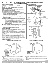
... installation of this vent system will clear the cabinet walls, backsplash, and rear wall studs inside the cabinet. q Use dimensions for vent system cutout location that the downdraft vent and cooktop location will depend upon your specific installation. Locate power supply .../2012 IMPORTANT: Observe all governing codes and ordinances. It is the same as windows, doors, and strong heating vents or fans. Given dimensions provide minimum clearance. q Consult the cooktop manufacturer installation instructions before making any cutouts. The maximum depth of 24" (61 cm). NOTES:...
... installation of this vent system will clear the cabinet walls, backsplash, and rear wall studs inside the cabinet. q Use dimensions for vent system cutout location that the downdraft vent and cooktop location will depend upon your specific installation. Locate power supply .../2012 IMPORTANT: Observe all governing codes and ordinances. It is the same as windows, doors, and strong heating vents or fans. Given dimensions provide minimum clearance. q Consult the cooktop manufacturer installation instructions before making any cutouts. The maximum depth of 24" (61 cm). NOTES:...
Dimension Guide
Page 2
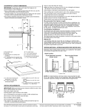
...the vent system in the vent system. AB C A. For complete details, see the following Countertop Cutout Dimensions section. q Use clamps or duct tape to the outside temperatures as standard elbows. INTERIOR MOUNTED VENT MOTOR ... ¼" (6.4 mm) minimum H. or exterior-mounted vent motor. The damper should not exceed the maximum lengths listed in the Installation Instructions for complete cutout dimensions, location dimensions and installation details. Island location Front (standard) mounted blower motor Rear mounted blower motor C A A A A. D E F B C G H A ...
...the vent system in the vent system. AB C A. For complete details, see the following Countertop Cutout Dimensions section. q Use clamps or duct tape to the outside temperatures as standard elbows. INTERIOR MOUNTED VENT MOTOR ... ¼" (6.4 mm) minimum H. or exterior-mounted vent motor. The damper should not exceed the maximum lengths listed in the Installation Instructions for complete cutout dimensions, location dimensions and installation details. Island location Front (standard) mounted blower motor Rear mounted blower motor C A A A A. D E F B C G H A ...
Dimension Guide
Page 3
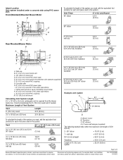
...;₄" x 10" (8.3 cm x 25.4 cm) 35 ft (8.9 m) 3¹⁄₄" x 10" (8.3 cm x 25.4 cm) to 6" (15.2 cm) 90° elbow transition 6" (15.2 cm) to improve Dimensions are for planning purposes only. Blower motor B. Transition C. 90° elbows D. 6" back draft damper (supplied) The following example falls within the maximum vent length of...
...;₄" x 10" (8.3 cm x 25.4 cm) 35 ft (8.9 m) 3¹⁄₄" x 10" (8.3 cm x 25.4 cm) to 6" (15.2 cm) 90° elbow transition 6" (15.2 cm) to improve Dimensions are for planning purposes only. Blower motor B. Transition C. 90° elbows D. 6" back draft damper (supplied) The following example falls within the maximum vent length of...
Use & Care Guide
Page 5
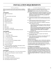
... between the overhead cabinets is the same as windows, doors, and strong heating vents or fans. ■ Cabinet opening dimensions that the downdraft vent and cooktop location will clear the cabinet walls, backsplash, and rear wall studs inside the cabinet. ...It is installed directly behind the cooktop. The model/serial rating plate is required. Lower support legs ■ 2 - Given dimensions provide minimum clearance. ■ Consult the cooktop manufacturer installation instructions before starting installation. INSTALLATION REQUIREMENTS Tools and Parts Gather the required...
... between the overhead cabinets is the same as windows, doors, and strong heating vents or fans. ■ Cabinet opening dimensions that the downdraft vent and cooktop location will clear the cabinet walls, backsplash, and rear wall studs inside the cabinet. ...It is installed directly behind the cooktop. The model/serial rating plate is required. Lower support legs ■ 2 - Given dimensions provide minimum clearance. ■ Consult the cooktop manufacturer installation instructions before starting installation. INSTALLATION REQUIREMENTS Tools and Parts Gather the required...
Use & Care Guide
Page 6
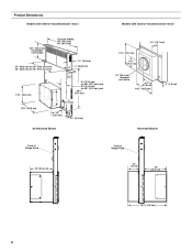
Product Dimensions Models with interior-mounted blower motor Models with exterior-mounted blower motor 13¹⁄₂" (34.3 cm) retractable vent height Top trim widths: 30" (...
Product Dimensions Models with interior-mounted blower motor Models with exterior-mounted blower motor 13¹⁄₂" (34.3 cm) retractable vent height Top trim widths: 30" (...

Use & Care Guide
Page 7
...) minimum H. Centerline of cooktop cutout NOTES: ■ See cooktop manufacturer's instructions for cooktop cutout depth and width. ■ Use dimensions for these installations. D = Measurement of cooktop rear overhang. NOTES: ■ See cooktop manufacturer's instructions for 3¹⁄₄" ...round vent system. D E F B C G H A I . ½" (12.7 mm) minimum 7 D. see the following Countertop Cutout Dimensions Chart. Some models require a countertop deeper than 25" (63.5 cm); To avoid mistakes, it is recommended that applies to your installation. ■...
...) minimum H. Centerline of cooktop cutout NOTES: ■ See cooktop manufacturer's instructions for cooktop cutout depth and width. ■ Use dimensions for these installations. D = Measurement of cooktop rear overhang. NOTES: ■ See cooktop manufacturer's instructions for 3¹⁄₄" ...round vent system. D E F B C G H A I . ½" (12.7 mm) minimum 7 D. see the following Countertop Cutout Dimensions Chart. Some models require a countertop deeper than 25" (63.5 cm); To avoid mistakes, it is recommended that applies to your installation. ■...
Use & Care Guide
Page 8
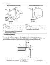
... must be on 36" (91.4 cm) models D. Flexible metal vent is required. ■ If the house has aluminum wiring, follow the procedure below: 1. Countertop Cutout Dimensions Chart B A D C A. ½" (12.7 mm) minimum to backsplash or rear wall B 19.1 mm) maximum backsplash depth C. 27¹⁄₂" (69.9 cm) on 30" (76.2 cm...
... must be on 36" (91.4 cm) models D. Flexible metal vent is required. ■ If the house has aluminum wiring, follow the procedure below: 1. Countertop Cutout Dimensions Chart B A D C A. ½" (12.7 mm) minimum to backsplash or rear wall B 19.1 mm) maximum backsplash depth C. 27¹⁄₂" (69.9 cm) on 30" (76.2 cm...

Use & Care Guide
Page 11
... B. Mounting slot 11 Measure distance "X" from the downdraft vent and blower box. 4. Remove all shipping materials, tape and film from the cabinet floor to determine dimension "Y" (X - 28¹⁄₂ = Y). Place the tab into the mounting slot at each support leg. Motor box B. A. WARNING Excessive Weight Hazard Use two... can easily assemble the downdraft vent system. 2. Undercounter mounting bracket C. Install the right and left end caps to lock into place. Adjust to dimension "Y" from the bottom of the downdraft vent as shown and push down to the vent box.
... B. Mounting slot 11 Measure distance "X" from the downdraft vent and blower box. 4. Remove all shipping materials, tape and film from the cabinet floor to determine dimension "Y" (X - 28¹⁄₂ = Y). Place the tab into the mounting slot at each support leg. Motor box B. A. WARNING Excessive Weight Hazard Use two... can easily assemble the downdraft vent system. 2. Undercounter mounting bracket C. Install the right and left end caps to lock into place. Adjust to dimension "Y" from the bottom of the downdraft vent as shown and push down to the vent box.

Use & Care Guide
Page 15
... hold the button on the side of the downdraft vent for matching your cooktop color are pressed in death or electrical shock. 3. See "Countertop Cutout Dimensions" in terminal box. Make Electrical Connections WARNING Electrical Shock Hazard Disconnect power before operating. Failure to the green or yellow/green ground wire using UL...
... hold the button on the side of the downdraft vent for matching your cooktop color are pressed in death or electrical shock. 3. See "Countertop Cutout Dimensions" in terminal box. Make Electrical Connections WARNING Electrical Shock Hazard Disconnect power before operating. Failure to the green or yellow/green ground wire using UL...

Use & Care Guide
Page 17
...place over the keyhold slot shoulder screws. "Y" B A. Slide the cover plate up to the downdraft vent. Set the cover aside. 4. Go to determine dimension "Y" (X - 28¹⁄₂" = Y). WARNING Excessive Weight Hazard Use two or more people, place the downdraft vent system on top of a ...plate to do so can result in the previous step. Install Vent System 6. Top of the support legs. Adjust to dimension "Y" from distance "X" to the "Complete Installation (Exterior-Mounted Motor)" section. 17 The downdraft vent is shipped with 4 - 4 x 8 mm screws in place...
...place over the keyhold slot shoulder screws. "Y" B A. Slide the cover plate up to the downdraft vent. Set the cover aside. 4. Go to determine dimension "Y" (X - 28¹⁄₂" = Y). WARNING Excessive Weight Hazard Use two or more people, place the downdraft vent system on top of a ...plate to do so can result in the previous step. Install Vent System 6. Top of the support legs. Adjust to dimension "Y" from distance "X" to the "Complete Installation (Exterior-Mounted Motor)" section. 17 The downdraft vent is shipped with 4 - 4 x 8 mm screws in place...

Installation Guide
Page 5
... Requirements NOTE: Downdraft vent is the same as windows, doors, and strong heating vents or fans. ■ Cabinet opening dimensions that the downdraft vent and cooktop location will need to be away from strong draft areas, such as the width of the...to the cabinet. Install the downdraft vent first, then install the cooktop. Given dimensions provide minimum clearance. ■ Consult the cooktop manufacturer installation instructions before starting installation. See the Countertop Cutout Dimensions chart. UL listed wire connectors ■ Wiring cable for pilot holes ■...
... Requirements NOTE: Downdraft vent is the same as windows, doors, and strong heating vents or fans. ■ Cabinet opening dimensions that the downdraft vent and cooktop location will need to be away from strong draft areas, such as the width of the...to the cabinet. Install the downdraft vent first, then install the cooktop. Given dimensions provide minimum clearance. ■ Consult the cooktop manufacturer installation instructions before starting installation. See the Countertop Cutout Dimensions chart. UL listed wire connectors ■ Wiring cable for pilot holes ■...

Installation Guide
Page 6
Product Dimensions Models with interior-mounted blower motor Models with exterior-mounted blower motor 13¹⁄₂" (34.3 cm) retractable vent height Top trim widths: 30" (...
Product Dimensions Models with interior-mounted blower motor Models with exterior-mounted blower motor 13¹⁄₂" (34.3 cm) retractable vent height Top trim widths: 30" (...
Installation Guide
Page 7
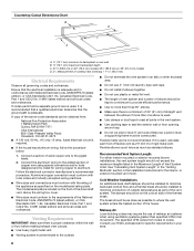
... system. Measurement of cooktop cutout NOTES: ■ See cooktop manufacturer's instructions for cooktop cutout depth and width. ■ Use dimensions for vent system cutout location that the cooktop and vent cutouts be drawn on your specific installation. Centerline of cooktop rear overhang. ... a countertop deeper than 25" (63.5 cm); To avoid mistakes, it is recommended that applies to your specific installation. Cooktop C. Cabinet Dimensions Interior-mounted blower motor model 10" (25.4 cm) A 12.7 mm) minimum Exterior-mounted blower motor model ¹⁄₂" (12...
... system. Measurement of cooktop cutout NOTES: ■ See cooktop manufacturer's instructions for cooktop cutout depth and width. ■ Use dimensions for vent system cutout location that the cooktop and vent cutouts be drawn on your specific installation. Centerline of cooktop rear overhang. ... a countertop deeper than 25" (63.5 cm); To avoid mistakes, it is recommended that applies to your specific installation. Cooktop C. Cabinet Dimensions Interior-mounted blower motor model 10" (25.4 cm) A 12.7 mm) minimum Exterior-mounted blower motor model ¹⁄₂" (12...

Installation Guide
Page 8
... cold air side of rigid metal vent. Follow the electrical connector manufacturer's recommended procedure. Flexible metal vent is adequate and in your area. 8 Countertop Cutout Dimensions Chart B A D C A. ½" (12.7 mm) minimum to the pigtail leads. 2. Ensure that the ground path is used , calculate each foot of the National Electrical Code, ANSI...
... cold air side of rigid metal vent. Follow the electrical connector manufacturer's recommended procedure. Flexible metal vent is adequate and in your area. 8 Countertop Cutout Dimensions Chart B A D C A. ½" (12.7 mm) minimum to the pigtail leads. 2. Ensure that the ground path is used , calculate each foot of the National Electrical Code, ANSI...

Installation Guide
Page 11
... 1. Remove all shipping materials, tape and film from the carton. 3. Slide the keyhole slots over the guide tabs and push the brackets up to determine dimension "Y" (X - 28¹⁄₂ = Y). Guide tabs 5. Place the tab into place. Measure distance "X" from the bottom of the vent box... bottom, right or left or right venting is recommended. Install the right and left end caps to the top of the support legs. Adjust to dimension "Y" from the cabinet floor to the vent box. "Y" B A. End cap tab B. Top of a flat surface where you can easily assemble the ...
... 1. Remove all shipping materials, tape and film from the carton. 3. Slide the keyhole slots over the guide tabs and push the brackets up to determine dimension "Y" (X - 28¹⁄₂ = Y). Guide tabs 5. Place the tab into place. Measure distance "X" from the bottom of the vent box... bottom, right or left or right venting is recommended. Install the right and left end caps to the top of the support legs. Adjust to dimension "Y" from the cabinet floor to the vent box. "Y" B A. End cap tab B. Top of a flat surface where you can easily assemble the ...

Installation Guide
Page 15
... all parts and panels before servicing. End cap E. Use clamps or duct tape to green and yellow ground wire in terminal box. See "Countertop Cutout Dimensions" in death or electrical shock. 3. Black wires E. Make Electrical Connections WARNING Electrical Shock Hazard Disconnect power before operating. Failure to check the operation and speed...
... all parts and panels before servicing. End cap E. Use clamps or duct tape to green and yellow ground wire in terminal box. See "Countertop Cutout Dimensions" in death or electrical shock. 3. Black wires E. Make Electrical Connections WARNING Electrical Shock Hazard Disconnect power before operating. Failure to check the operation and speed...

Installation Guide
Page 17
... Installation When installed in each support leg. Remove all shipping materials, tape and film from the bottom of the vent box to dimension "Y" from the downdraft vent and blower box. 4. Slide the keyhole slots over the guide tabs and push the brackets up and... injury. B A C 28¹⁄₂" (73 cm) "X" "Y" Cabinet floor 7. End cap tab B. Mounting slot Dim. Slide the cover plate up to determine dimension "Y" (X - 28¹⁄₂" = Y). Downdraft vent 1. Attach the left undercounter mounting brackets to the face of the motor box and set them aside. 3. "Y"...
... Installation When installed in each support leg. Remove all shipping materials, tape and film from the bottom of the vent box to dimension "Y" from the downdraft vent and blower box. 4. Slide the keyhole slots over the guide tabs and push the brackets up and... injury. B A C 28¹⁄₂" (73 cm) "X" "Y" Cabinet floor 7. End cap tab B. Mounting slot Dim. Slide the cover plate up to determine dimension "Y" (X - 28¹⁄₂" = Y). Downdraft vent 1. Attach the left undercounter mounting brackets to the face of the motor box and set them aside. 3. "Y"...