Dimension Guide
Page 1
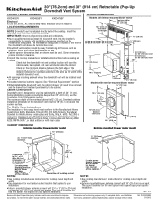
... as windows, doors, and strong heating vents or fans. q Downdraft vent location should be removed and the drawer front installed permanently to change materials and specifications without notice. See "Electrical Requirements" section. q Cabinet opening dimensions that the downdraft vent and...vent above the cooking surface. IMPORTANT: Observe all governing codes and ordinances. It is not applicable, the standard for planning purposes only. Some installations require a countertop deeper than 25" (63.5 cm). 30" (76.2 cm) and 36" (91.4 cm) Retractable (Pop-Up) ...
... as windows, doors, and strong heating vents or fans. q Downdraft vent location should be removed and the drawer front installed permanently to change materials and specifications without notice. See "Electrical Requirements" section. q Cabinet opening dimensions that the downdraft vent and...vent above the cooking surface. IMPORTANT: Observe all governing codes and ordinances. It is not applicable, the standard for planning purposes only. Some installations require a countertop deeper than 25" (63.5 cm). 30" (76.2 cm) and 36" (91.4 cm) Retractable (Pop-Up) ...
Dimension Guide
Page 2
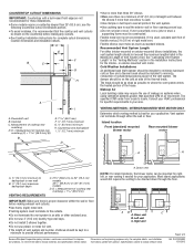
... vent between the elbows if more than 25" (63.5 cm); q Do not terminate the vent system in the Installation Instructions for these installations. q Do not install 2 elbows together. Specifications subject to improve Dimensions are not recommended for the interior- W10342489D 1/31/2012 Downdraft vent B.... may require the use of rigid metal vent. Flexible metal vent is used , calculate each foot of cooktop rear overhang. see Installation our products, we reserve the right to seal all joints in your application. Vent system can be constructed. q Use heavy (...
... vent between the elbows if more than 25" (63.5 cm); q Do not terminate the vent system in the Installation Instructions for these installations. q Do not install 2 elbows together. Specifications subject to improve Dimensions are not recommended for the interior- W10342489D 1/31/2012 Downdraft vent B.... may require the use of rigid metal vent. Flexible metal vent is used , calculate each foot of cooktop rear overhang. see Installation our products, we reserve the right to seal all joints in your application. Vent system can be constructed. q Use heavy (...
Dimension Guide
Page 3
...cm x 25.4 cm) to 6" (15.2 cm) 90° elbow transition 6" (15.2 cm) to change without notice. W10342489D 1/31/2012 For complete details, see Installation our products, we reserve the right to 3¹⁄₄" x 10" (8.3 cm x 25.4 cm) 90° elbow transition Example vent system C A B D... (15.2 cm) system = 22.5 ft (6.8 m) Page 3 of 35 ft (8.9 m). 2 - 90° elbow = 10.0 ft (3 m) 1 - Island Location Vent system installed under a concrete slab using PVC sewer pipe. K. 6" (15.2 cm) round 90° PVC sewer pipe elbow L. 6" (15.2 cm) round PVC coupling M. 12" (30.5 ...
...cm x 25.4 cm) to 6" (15.2 cm) 90° elbow transition 6" (15.2 cm) to change without notice. W10342489D 1/31/2012 For complete details, see Installation our products, we reserve the right to 3¹⁄₄" x 10" (8.3 cm x 25.4 cm) 90° elbow transition Example vent system C A B D... (15.2 cm) system = 22.5 ft (6.8 m) Page 3 of 35 ft (8.9 m). 2 - 90° elbow = 10.0 ft (3 m) 1 - Island Location Vent system installed under a concrete slab using PVC sewer pipe. K. 6" (15.2 cm) round 90° PVC sewer pipe elbow L. 6" (15.2 cm) round PVC coupling M. 12" (30.5 ...
Use & Care Guide
Page 4
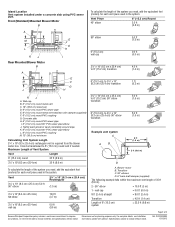
... your back to an exit. you may ignite. Follow the heating equipment manufacturer's guideline and safety standards such as a tag, to the service panel. ■ Installation work and electrical wiring must always be allowed to exhaust hazardous or explosive materials and vapors. do not use cookware appropriate for proper combustion and...
... your back to an exit. you may ignite. Follow the heating equipment manufacturer's guideline and safety standards such as a tag, to the service panel. ■ Installation work and electrical wiring must always be allowed to exhaust hazardous or explosive materials and vapors. do not use cookware appropriate for proper combustion and...
Use & Care Guide
Page 5
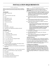
...Tools Needed ■ Jigsaw or keyhole saw ■ Drill 3 mm) drill bit for use in ceiling and wall where the downdraft vent will be installed must conform to match vent system ■ Vent system ■ Home power supply cable ■ 3 - mounted blower motor models only) ■...9632; Grounded electrical outlet is the same as required Location Requirements NOTE: Downdraft vent is not applicable, the standard for Manufactured Home Installation 1982 (Manufactured Home Sites, Communities and Setups) ANSI A225.1/NFPA 501A*, or latest edition, or with damper to the Manufactured Home ...
...Tools Needed ■ Jigsaw or keyhole saw ■ Drill 3 mm) drill bit for use in ceiling and wall where the downdraft vent will be installed must conform to match vent system ■ Vent system ■ Home power supply cable ■ 3 - mounted blower motor models only) ■...9632; Grounded electrical outlet is the same as required Location Requirements NOTE: Downdraft vent is not applicable, the standard for Manufactured Home Installation 1982 (Manufactured Home Sites, Communities and Setups) ANSI A225.1/NFPA 501A*, or latest edition, or with damper to the Manufactured Home ...

Use & Care Guide
Page 7
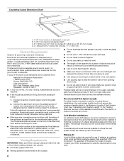
... ¹⁄₂" (12.7 mm) minimum 21 54.1 cm) 21 54.1 cm) Cutouts are not recommended for these installations. Countertop Cutout Dimensions IMPORTANT: Countertops with a bull-nosed front edge are for vent system cutout location that the cooktop and vent... cutouts be drawn on your installation. ■ Interior-mounted blower systems connect with 10" (25.4 cm) round vent. Centerline of the cabinet. Cooktop C. Measurement of cooktop rear...
... ¹⁄₂" (12.7 mm) minimum 21 54.1 cm) 21 54.1 cm) Cutouts are not recommended for these installations. Countertop Cutout Dimensions IMPORTANT: Countertops with a bull-nosed front edge are for vent system cutout location that the cooktop and vent... cutouts be drawn on your installation. ■ Interior-mounted blower systems connect with 10" (25.4 cm) round vent. Centerline of the cabinet. Cooktop C. Measurement of cooktop rear...
Use & Care Guide
Page 8
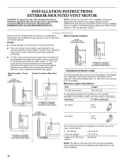
...area. 8 Connect a section of solid copper wire to locale. Recommended Vent System Length: For either interior-mounted or exterior-mounted blower installations, the vent system length should be kept to a minimum to provide efficient performance. ■ Use no more than three 90° ...;" (85.9 cm) on the model/serial rating plate. See "Calculating Vent System Length" in the "Venting Methods" section in the Installation Instructions for specific requirements in the Maximum Length of Vent System chart. The specified CFM varies from : National Fire Protection Association 1 Batterymarch...
...area. 8 Connect a section of solid copper wire to locale. Recommended Vent System Length: For either interior-mounted or exterior-mounted blower installations, the vent system length should be kept to a minimum to provide efficient performance. ■ Use no more than three 90° ...;" (85.9 cm) on the model/serial rating plate. See "Calculating Vent System Length" in the "Venting Methods" section in the Installation Instructions for specific requirements in the Maximum Length of Vent System chart. The specified CFM varies from : National Fire Protection Association 1 Batterymarch...
Use & Care Guide
Page 9
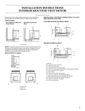
...or left venting if needed for your application. Concrete slab H. 6" (15.2 cm) round PVC sewer pipe I A. INSTALLATION INSTRUCTIONS INTERIOR-MOUNTED VENT MOTOR Venting Methods Determine which venting method is best for your application. Built-In Cabinet Locations Rear...pipe E. 6" (15.2 cm) round metal vent transition with damper (supplied) F. 6" (15.2 cm) round PVC coupling G. Island Location-Vent System Installed Under a Concrete Slab Using PVC Sewer Pipe Island Location Front (Standard)-Mounted Blower Motor Rear-Mounted Blower Motor Front (Standard)-Mounted Blower Motor B A ...
...or left venting if needed for your application. Concrete slab H. 6" (15.2 cm) round PVC sewer pipe I A. INSTALLATION INSTRUCTIONS INTERIOR-MOUNTED VENT MOTOR Venting Methods Determine which venting method is best for your application. Built-In Cabinet Locations Rear...pipe E. 6" (15.2 cm) round metal vent transition with damper (supplied) F. 6" (15.2 cm) round PVC coupling G. Island Location-Vent System Installed Under a Concrete Slab Using PVC Sewer Pipe Island Location Front (Standard)-Mounted Blower Motor Rear-Mounted Blower Motor Front (Standard)-Mounted Blower Motor B A ...

Use & Care Guide
Page 11
...Undercounter mounting bracket C. Place the tab into place. NOTE: When using the 6" (15.2 cm) vent transition (supplied) for Your Installation When installed in place. A. Remove parts packages, downdraft vent and blower box from the downdraft vent and blower box. 4. Tighten screws. Guide... tabs 5. Measure distance "X" from distance "X" to move and install downdraft vent. Keyhole slots D. Support leg C. 4 x 8 mm screws (4) Determine Which Vent Direction Is Best for 6" round venting, ...
...Undercounter mounting bracket C. Place the tab into place. NOTE: When using the 6" (15.2 cm) vent transition (supplied) for Your Installation When installed in place. A. Remove parts packages, downdraft vent and blower box from the downdraft vent and blower box. 4. Tighten screws. Guide... tabs 5. Measure distance "X" from distance "X" to move and install downdraft vent. Keyhole slots D. Support leg C. 4 x 8 mm screws (4) Determine Which Vent Direction Is Best for 6" round venting, ...

Use & Care Guide
Page 12
... or right side of the motor box for island cabinet locations. Do not twist or bind the wires. 7. Reinstall the cover plate to the "Complete Installation (Interior-Mounted Motor)" section. 12 C B A. Screws (7) B. Screws (6) B. Motor mounting screws (4) E. Slide the cover plate up and slip it ...3 screws and the vent cover plate from the left or right side to the chosen venting direction and secure to the motor box. Install the vent cover plate over the keyhole slot shoulder screws. NOTE: Reinstall the electrical wiring connection to the "Rear Mounting - Blower Motor...
... or right side of the motor box for island cabinet locations. Do not twist or bind the wires. 7. Reinstall the cover plate to the "Complete Installation (Interior-Mounted Motor)" section. 12 C B A. Screws (7) B. Screws (6) B. Motor mounting screws (4) E. Slide the cover plate up and slip it ...3 screws and the vent cover plate from the left or right side to the chosen venting direction and secure to the motor box. Install the vent cover plate over the keyhole slot shoulder screws. NOTE: Reinstall the electrical wiring connection to the "Rear Mounting - Blower Motor...

Use & Care Guide
Page 13
... NOTE: The downdraft vent system is recommended), using . 3¹⁄₄" x 10" (8.3 x 25.4 cm) Back Draft Damper 1. Install the wire mounting plate to the front of the mounting plate. Mount the 4³⁄₄" (12.0 cm) cover box (supplied) to ... assembly through the slot in the blower motor box, using the 4 screws previously removed. 11. Reassemble the wire assembly and grommet to the "Complete Installation (Interior-Mounted Motor)" section. Wire mounting plate C. Mount the blower motor box to vent box using the 6 screws previously removed. 13. Screws B....
... NOTE: The downdraft vent system is recommended), using . 3¹⁄₄" x 10" (8.3 x 25.4 cm) Back Draft Damper 1. Install the wire mounting plate to the front of the mounting plate. Mount the 4³⁄₄" (12.0 cm) cover box (supplied) to ... assembly through the slot in the blower motor box, using the 4 screws previously removed. 11. Reassemble the wire assembly and grommet to the "Complete Installation (Interior-Mounted Motor)" section. Wire mounting plate C. Mount the blower motor box to vent box using the 6 screws previously removed. 13. Screws B....

Use & Care Guide
Page 14
... box cover. IMPORTANT: Select a screw length that the downdraft vent is centered in countertop C. Remove the appropriate knockout from the front or rear panel and install a ¹⁄₂" (12.7 mm) UL listed or CSA approved conduit connector. 4. Countertop 6. Cabinet back E. A 5. Tighten the lower support legs screws. E F A. Edge of the cutout...
... box cover. IMPORTANT: Select a screw length that the downdraft vent is centered in countertop C. Remove the appropriate knockout from the front or rear panel and install a ¹⁄₂" (12.7 mm) UL listed or CSA approved conduit connector. 4. Countertop 6. Cabinet back E. A 5. Tighten the lower support legs screws. E F A. Edge of the cutout...

Use & Care Guide
Page 15
... on the top of vent to blower. Connect vent system to check the operation and speed of retractable downdraft vent by ³⁄₈" (9.5 mm). Install cooktop according to green and yellow ground wire in death or electrical shock. 1. See "Countertop Cutout Dimensions" in the "Location Requirements" section. NOTE: To get...
... on the top of vent to blower. Connect vent system to check the operation and speed of retractable downdraft vent by ³⁄₈" (9.5 mm). Install cooktop according to green and yellow ground wire in death or electrical shock. 1. See "Countertop Cutout Dimensions" in the "Location Requirements" section. NOTE: To get...
Use & Care Guide
Page 16
... round vents - 60 ft (18.3 m). 2 - 90° elbows = 10.0 ft (3 m) 10 ft (3 m) straight = 10.0 ft (3 m) Length of fire and electrical shock, install the downdraft only with remote blower systems that you use round vent instead of the system you need, add the equivalent feet (meters) for the... ■ Venting through the wall or roof. To basement, crawlspace or utility room installed in-line blower motor system Calculating Vent System Length Island Location-Front Vent To attic installed in-line blower motor system Island Location-Rear Vent It is recommended for each vent piece...
... round vents - 60 ft (18.3 m). 2 - 90° elbows = 10.0 ft (3 m) 10 ft (3 m) straight = 10.0 ft (3 m) Length of fire and electrical shock, install the downdraft only with remote blower systems that you use round vent instead of the system you need, add the equivalent feet (meters) for the... ■ Venting through the wall or roof. To basement, crawlspace or utility room installed in-line blower motor system Calculating Vent System Length Island Location-Front Vent To attic installed in-line blower motor system Island Location-Rear Vent It is recommended for each vent piece...

Use & Care Guide
Page 17
... Motor box B. Using two or more people to the top of the vent box. Subtract 28¹⁄₂" from distance "X" to the "Complete Installation (Exterior-Mounted Motor)" section. 17 Remove parts packages, downdraft vent and blower box from the downdraft vent and blower box. 4. D C A A. ...Direction Is Best for venting. 2. Front or Rear Venting: 1. Place cardboard or similar material on the opposite side for Your Installation When installed in a cabinet the vent system can exhaust through the front or rear of the countertop. Remove all shipping materials, tape and...
... Motor box B. Using two or more people to the top of the vent box. Subtract 28¹⁄₂" from distance "X" to the "Complete Installation (Exterior-Mounted Motor)" section. 17 Remove parts packages, downdraft vent and blower box from the downdraft vent and blower box. 4. D C A A. ...Direction Is Best for venting. 2. Front or Rear Venting: 1. Place cardboard or similar material on the opposite side for Your Installation When installed in a cabinet the vent system can exhaust through the front or rear of the countertop. Remove all shipping materials, tape and...

Use & Care Guide
Page 18
Determine which direction (front or rear) the home power supply cable and the wiring conduit from the front or rear panel and install two ¹⁄₂" (12.7 mm) UL listed or CSA approved conduit connectors. 3. Countertop 5. Loosen the lower support legs...back E. Prepare for Mounting the In-Line Blower System The in -line (external type) blower motor system. Complete Installation (Exterior-Mounted Motor) 1. Screws B. Screw (not provided) 7. Install Downdraft Vent In-Line (External Type) Blower Motor NOTE: Your downdraft vent requires you to the cabinet floor with the...
Determine which direction (front or rear) the home power supply cable and the wiring conduit from the front or rear panel and install two ¹⁄₂" (12.7 mm) UL listed or CSA approved conduit connectors. 3. Countertop 5. Loosen the lower support legs...back E. Prepare for Mounting the In-Line Blower System The in -line (external type) blower motor system. Complete Installation (Exterior-Mounted Motor) 1. Screws B. Screw (not provided) 7. Install Downdraft Vent In-Line (External Type) Blower Motor NOTE: Your downdraft vent requires you to the cabinet floor with the...

Use & Care Guide
Page 19
... motor electrical plug from the housing and place it is removed, reattach the motor electrical plug to release the blower motor assembly. Motor electrical plug Install In-line Blower System NOTE: The blower motor housing can be mounted using a 4.8 mm) drill bit. 3. Drill 4 mounting pilot holes using...to the mounting location. 2. Failure to mount, the blower motor assembly can result in this location. 19 Using 2 or more people to "Install In-line Blower System" in back or other hidden utilities. 2. NOTE: To make all necessary cuts for the vent system. If you do...
... motor electrical plug from the housing and place it is removed, reattach the motor electrical plug to release the blower motor assembly. Motor electrical plug Install In-line Blower System NOTE: The blower motor housing can be mounted using a 4.8 mm) drill bit. 3. Drill 4 mounting pilot holes using...to the mounting location. 2. Failure to mount, the blower motor assembly can result in this location. 19 Using 2 or more people to "Install In-line Blower System" in back or other hidden utilities. 2. NOTE: To make all necessary cuts for the vent system. If you do...

Use & Care Guide
Page 20
Make Electrical Connections for the installation of the UL listed or CSA approved ¹⁄₂" (1.3 cm) wiring conduit and conduit connector. 6. Electrical Shock Hazard Disconnect power before operating. Disconnect power. 2. ...;⁄₂" (1.3 cm) wiring conduit and conduit connectors and into the terminal boxes on the in -line blower housing and downdraft vent electrical terminal boxes. 9. Install the conduit connectors and conduit to do so can result in -line blower housing and downdraft vent. 7. Connect the vent system to prepare for In...
Make Electrical Connections for the installation of the UL listed or CSA approved ¹⁄₂" (1.3 cm) wiring conduit and conduit connector. 6. Electrical Shock Hazard Disconnect power before operating. Disconnect power. 2. ...;⁄₂" (1.3 cm) wiring conduit and conduit connectors and into the terminal boxes on the in -line blower housing and downdraft vent electrical terminal boxes. 9. Install the conduit connectors and conduit to do so can result in -line blower housing and downdraft vent. 7. Connect the vent system to prepare for In...

Use & Care Guide
Page 22
... matching your cooktop color are pressed in terminal box using UL listed wire connectors. 6. On/Off button C. Filters 2. WARNING Electrical Shock Hazard Electrically ground blower. Install terminal box cover. 7. Connect green (or bare) ground wire from the In-line blower motor system is to blower. Top trim B. NOTE: To get the...
... matching your cooktop color are pressed in terminal box using UL listed wire connectors. 6. On/Off button C. Filters 2. WARNING Electrical Shock Hazard Electrically ground blower. Install terminal box cover. 7. Connect green (or bare) ground wire from the In-line blower motor system is to blower. Top trim B. NOTE: To get the...

Use & Care Guide
Page 24
... that they lock into place. Pull the spring release handle down the filter. 2. If Retractable Downdraft Vent Does Not Operate After Clean Filters Have Been Installed: Push the filter in as far as needed in place. 2. A B C A. Cleaning Method: ■ Liquid detergent soap and water, or ... a dishwasher or in the retractable section of the downdraft vent. When the filter is removed, the microswitch behind the filter is properly installed. The downdraft vent will go. Right metal filter 24 To Clean: 1. Push up on metal filter and release handle to avoid water...
... that they lock into place. Pull the spring release handle down the filter. 2. If Retractable Downdraft Vent Does Not Operate After Clean Filters Have Been Installed: Push the filter in as far as needed in place. 2. A B C A. Cleaning Method: ■ Liquid detergent soap and water, or ... a dishwasher or in the retractable section of the downdraft vent. When the filter is removed, the microswitch behind the filter is properly installed. The downdraft vent will go. Right metal filter 24 To Clean: 1. Push up on metal filter and release handle to avoid water...
