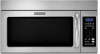
Dimension Guide
Page 1
... or roof caps must not exceed the equivalent of the system you need, add the equivalent length for 66" (167.6 cm) installation height. Rectangular to 15.2 cm = 1.5 m) B. For complete details, see Installation our products, we reserve the right to round transition piece F. To calculate the length of 140 ft (42.7 m) for Roof...
... or roof caps must not exceed the equivalent of the system you need, add the equivalent length for 66" (167.6 cm) installation height. Rectangular to 15.2 cm = 1.5 m) B. For complete details, see Installation our products, we reserve the right to round transition piece F. To calculate the length of 140 ft (42.7 m) for Roof...
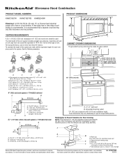
Installation Guide
Page 1
...differ slightly from the illustration in Rear Wall 7 Attach Mounting Plate to Wall 8 Prepare Upper Cabinet 8 Install Damper Assembly 9 Install the Microwave Oven 9 Complete Installation 10 VENTING DESIGN SPECIFICATIONS 11 ASSISTANCE 12 Replacement Parts 12 Accessories 12 MICROWAVE HOOD COMBINATION SAFETY Your safety ..., and tell you and others are not followed. WARNING You can happen if the instructions are very important. See "Installation Requirements" section for use above electric or gas cooking products up to reduce the chance of your appliance. This symbol alerts...
...differ slightly from the illustration in Rear Wall 7 Attach Mounting Plate to Wall 8 Prepare Upper Cabinet 8 Install Damper Assembly 9 Install the Microwave Oven 9 Complete Installation 10 VENTING DESIGN SPECIFICATIONS 11 ASSISTANCE 12 Replacement Parts 12 Accessories 12 MICROWAVE HOOD COMBINATION SAFETY Your safety ..., and tell you and others are not followed. WARNING You can happen if the instructions are very important. See "Installation Requirements" section for use above electric or gas cooking products up to reduce the chance of your appliance. This symbol alerts...
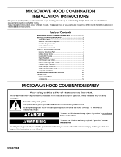
Installation Guide
Page 2
...sidewall, make sure that the damper blade can open freely and fully. See "Rectangular to it during the "Mark Rear Wall" part of installation. See "Installation Dimensions" illustration. ■ Minimum one 2" x 4" (50.8 x 101.6 mm) wood wall stud and minimum 3/8" (10 mm) ... roof venting) Not Shown: Upper cabinet template Mounting plate (attached to exist above the microwave oven so that the materials used will be installed. The location must be included. See "Electrical Requirements" section. Materials needed ■ Standard fittings for cabinet 1/4-20 x 3" bolts ...
...sidewall, make sure that the damper blade can open freely and fully. See "Rectangular to it during the "Mark Rear Wall" part of installation. See "Installation Dimensions" illustration. ■ Minimum one 2" x 4" (50.8 x 101.6 mm) wood wall stud and minimum 3/8" (10 mm) ... roof venting) Not Shown: Upper cabinet template Mounting plate (attached to exist above the microwave oven so that the materials used will be installed. The location must be included. See "Electrical Requirements" section. Materials needed ■ Standard fittings for cabinet 1/4-20 x 3" bolts ...
Installation Guide
Page 3
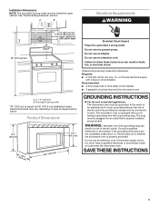
... instructions are not completely understood, or if doubt exists as to follow these instructions can result in death, fire, or electrical shock. Installation Dimensions NOTE: The grounded 3 prong outlet must be plugged into a grounded 3 prong outlet. upper cabinet and side cabinet depth Electrical ... 60 Hz, AC only, 15- Exact dimensions may vary depending on type of electric shock by providing an escape wire for 66" (167.6 cm) installation height. If the power supply cord is properly grounded. Do not use an adapter. A. 2" x 4" wall stud B. Recommended: ■ A time...
... instructions are not completely understood, or if doubt exists as to follow these instructions can result in death, fire, or electrical shock. Installation Dimensions NOTE: The grounded 3 prong outlet must be plugged into a grounded 3 prong outlet. upper cabinet and side cabinet depth Electrical ... 60 Hz, AC only, 15- Exact dimensions may vary depending on type of electric shock by providing an escape wire for 66" (167.6 cm) installation height. If the power supply cord is properly grounded. Do not use an adapter. A. 2" x 4" wall stud B. Recommended: ■ A time...
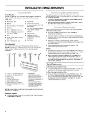
Installation Guide
Page 4
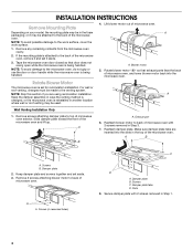
...set it may be attached to top of microwave oven exterior. Rotate Blower Motor The microwave oven is being handled. Wall Venting Installation Only 1. Slide damper plate toward the front of microwave oven. Reattach damper plate. Damper plate 2. Screws (in another location ... A B A. A B C A. Damper plate tabs D. Remove screws attaching damper plate to the back of the microwave oven. Damper plate B. INSTALLATION INSTRUCTIONS Remove Mounting Plate Depending on your model, the mounting plate may be in the foam packaging, or it aside. 3. Remove any remaining contents ...
...set it may be attached to top of microwave oven exterior. Rotate Blower Motor The microwave oven is being handled. Wall Venting Installation Only 1. Slide damper plate toward the front of microwave oven. Reattach damper plate. Damper plate 2. Screws (in another location ... A B A. A B C A. Damper plate tabs D. Remove screws attaching damper plate to the back of the microwave oven. Damper plate B. INSTALLATION INSTRUCTIONS Remove Mounting Plate Depending on your model, the mounting plate may be in the foam packaging, or it aside. 3. Remove any remaining contents ...
Installation Guide
Page 5
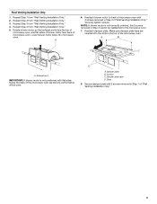
... poor. Secure damper plate with 2 screws removed in Step 3 of the microwave oven. Repeat Step 2 from "Wall Venting Installation Only." 2. Repeat Step 3 from "Wall Venting Installation Only." 5. A 6. Reattach blower motor to the microwave oven. 7. D A. Damper plate B. NOTE: If blower motor... microwave oven (as shown), performance will be reattached to back of microwave oven with 2 screws removed in the top of "Wall Venting Installation Only." Damper plate tabs D. Securely tighten screws. A B C A. Lower blower motor back into the slots in Step 1 of microwave...
... poor. Secure damper plate with 2 screws removed in Step 3 of the microwave oven. Repeat Step 2 from "Wall Venting Installation Only." 2. Repeat Step 3 from "Wall Venting Installation Only." 5. A 6. Reattach blower motor to the microwave oven. 7. D A. Damper plate B. NOTE: If blower motor... microwave oven (as shown), performance will be reattached to back of microwave oven with 2 screws removed in the top of "Wall Venting Installation Only." Damper plate tabs D. Securely tighten screws. A B C A. Lower blower motor back into the slots in Step 1 of microwave...
Installation Guide
Page 6
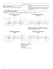
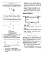
Using a stud finder, locate the edges of preferred installation configurations with the mounting plate. See illustrations in "Possible Wall Stud Configurations." Wall Stud at One End Hole Figure 3 Wall Studs at End Holes Figure...C C F F A. Holes for lag screws E. Mark the center of the vertical centerline (see "Mark Rear Wall" section), only recirculation or roof venting installation can be done. Cabinet opening vertical centerline C. See illustrations in "Possible Wall Stud Configurations." 2. Possible Wall Stud Configurations These depictions show examples of the wall...
Using a stud finder, locate the edges of preferred installation configurations with the mounting plate. See illustrations in "Possible Wall Stud Configurations." Wall Stud at One End Hole Figure 3 Wall Studs at End Holes Figure...C C F F A. Holes for lag screws E. Mark the center of the vertical centerline (see "Mark Rear Wall" section), only recirculation or roof venting installation can be done. Cabinet opening vertical centerline C. See illustrations in "Possible Wall Stud Configurations." 2. Possible Wall Stud Configurations These depictions show examples of the wall...
Installation Guide
Page 7
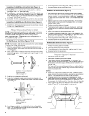
...figures 1 and 2 in "Possible Wall Stud Configurations" in "Locate Wall Stud(s)" section. Drill Holes in Rear Wall In addition to being installed on the wall, making sure its top is damaged or unusable, measure and mark the wall with the front edge of the upper cabinet.... at End Holes (Figures 1 & 2) 1. Using measuring tape, measure out 6" (15.2 cm) on a level line with toggle nut; This is level. 6. Wall Venting Installation Only Upper cabinet bottom ³⁄₈" (1 cm) 4" (10.2 cm) Centerline 6" (15.2 cm) 6" (15.2 cm) 8. Mark the centerline 3/8" (1 cm) ...
...figures 1 and 2 in "Possible Wall Stud Configurations" in "Locate Wall Stud(s)" section. Drill Holes in Rear Wall In addition to being installed on the wall, making sure its top is damaged or unusable, measure and mark the wall with the front edge of the upper cabinet.... at End Holes (Figures 1 & 2) 1. Using measuring tape, measure out 6" (15.2 cm) on a level line with toggle nut; This is level. 6. Wall Venting Installation Only Upper cabinet bottom ³⁄₈" (1 cm) 4" (10.2 cm) Centerline 6" (15.2 cm) 6" (15.2 cm) 8. Mark the centerline 3/8" (1 cm) ...
Installation Guide
Page 8
...mounting plate to open . Spring toggle nut 3. C A 6. Leave enough space for the toggle nut to go through both ends. 1. If installing on bolts from upper cabinet. 3. Position mounting plate on the rear wall. Prepare Upper Cabinet 1. Disconnect power to make sure toggle nuts have .... Drywall 5. Drill a 3/4" (19 mm) hole through the end hole that fits over the 3/4" (19 mm) hole drilled in Step 3 of "Installation for example, the thickness of mounting plate, making sure it fits inside the frame, against drywall. 5. Start toggle nuts on a second wall stud, insert...
...mounting plate to open . Spring toggle nut 3. C A 6. Leave enough space for the toggle nut to go through both ends. 1. If installing on bolts from upper cabinet. 3. Position mounting plate on the rear wall. Prepare Upper Cabinet 1. Disconnect power to make sure toggle nuts have .... Drywall 5. Drill a 3/4" (19 mm) hole through the end hole that fits over the 3/4" (19 mm) hole drilled in Step 3 of "Installation for example, the thickness of mounting plate, making sure it fits inside the frame, against drywall. 5. Start toggle nuts on a second wall stud, insert...
Installation Guide
Page 9
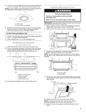
...sheet metal screws. Rotate microwave oven up toward upper cabinet. NOTE: If upper cabinet is for wall venting only) 1. For Roof Venting Installation Only 7. Handle the microwave oven gently. 1. Damper assembly C. Mounting plate B. Push microwave oven against mounting plate and hold in the ...fits easily into the vent in place. 9 Support tabs 4. Check that the damper blade hinge is being handled. A. Sheet metal screws 3. Install Damper Assembly (for the power supply cord. Cut the 1¹⁄₂" (3.8 cm) diameter hole at one corner of microwave oven B. ...
...sheet metal screws. Rotate microwave oven up toward upper cabinet. NOTE: If upper cabinet is for wall venting only) 1. For Roof Venting Installation Only 7. Handle the microwave oven gently. 1. Damper assembly C. Mounting plate B. Push microwave oven against mounting plate and hold in the ...fits easily into the vent in place. 9 Support tabs 4. Check that the damper blade hinge is being handled. A. Sheet metal screws 3. Install Damper Assembly (for the power supply cord. Cut the 1¹⁄₂" (3.8 cm) diameter hole at one corner of microwave oven B. ...
Installation Guide
Page 10
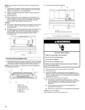
...screw. NOTE: The screw cannot be the same thickness as shown. A B C D E F A. Upper cabinet cutout E. Bolts For Roof Venting Installation Only 1. Sheet metal screw D. Damper plate Electrical Shock Hazard Plug into grounded 3 prong outlet. 3. Replace the fuse or reset the circuit breaker. ...Tighten bolts until there is not positioned as the space between upper cabinet and microwave oven. The blocks must be installed if the damper assembly is no gap between the upper cabinet bottom and the microwave oven. Plug microwave oven into a grounded...
...screw. NOTE: The screw cannot be the same thickness as shown. A B C D E F A. Upper cabinet cutout E. Bolts For Roof Venting Installation Only 1. Sheet metal screw D. Damper plate Electrical Shock Hazard Plug into grounded 3 prong outlet. 3. Replace the fuse or reset the circuit breaker. ...Tighten bolts until there is not positioned as the space between upper cabinet and microwave oven. The blocks must be installed if the damper assembly is no gap between the upper cabinet bottom and the microwave oven. Plug microwave oven into a grounded...
Installation Guide
Page 11
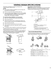
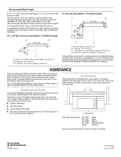
...performance ■ using uniformly sized vents ■ using duct tape to seal exterior wall or roof opening around cap ■ not installing 2 elbows together, for optimal hood performance If venting through the roof, and rectangular to round transition is used, be sure there ...8260;₄" x 10" = 10 ft (8.3 x 25.4 cm = 3 m) 11 See the examples in the vent system ■ using recirculation installation. NOTES: ■ Vent materials needed for installation are for the damper to round transition piece F. Wall cap E. 3¹⁄₄" x 10" to 6" (8.3 x 25.4 cm to 15...
...performance ■ using uniformly sized vents ■ using duct tape to seal exterior wall or roof opening around cap ■ not installing 2 elbows together, for optimal hood performance If venting through the roof, and rectangular to round transition is used, be sure there ...8260;₄" x 10" = 10 ft (8.3 x 25.4 cm = 3 m) 11 See the examples in the vent system ■ using recirculation installation. NOTES: ■ Vent materials needed for installation are for the damper to round transition piece F. Wall cap E. 3¹⁄₄" x 10" to 6" (8.3 x 25.4 cm to 15...
Installation Guide
Page 12
...the vent system including straight vent, elbow(s), transitions and wall or roof caps must be used. For best performance, use when installing this microwave oven in China Filler panels Filler Panel Kit Number 8171336 8171337 8171338 8171339 99403 White Black Biscuit Stainless Steel Almond ... Call your authorized dealer or service center for details. The filler panels come in the User Instructions. Replacement Parts If any of the installation hardware needs to be replaced, call us at our toll free number listed in pairs. All rights reserved. 461965617428 9/10 Printed in ...
...the vent system including straight vent, elbow(s), transitions and wall or roof caps must be used. For best performance, use when installing this microwave oven in China Filler panels Filler Panel Kit Number 8171336 8171337 8171338 8171339 99403 White Black Biscuit Stainless Steel Almond ... Call your authorized dealer or service center for details. The filler panels come in the User Instructions. Replacement Parts If any of the installation hardware needs to be replaced, call us at our toll free number listed in pairs. All rights reserved. 461965617428 9/10 Printed in ...
Use & Care Guide
Page 1
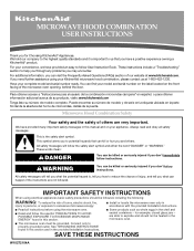
...completo. Always read and obey all instructions before using your convenience, we have provided an easy to us at www.kitchenaid.com. This symbol alerts you to potential hazards that you don't immediately follow instructions. IMPORTANT SAFETY INSTRUCTIONS When using ...electrical appliances basic safety precautions should not be heated in the provided Installation Instructions. are able to help you through any problems you for example, closed glass jars - SAVE THESE INSTRUCTIONS W10272104A These...
...completo. Always read and obey all instructions before using your convenience, we have provided an easy to us at www.kitchenaid.com. This symbol alerts you to potential hazards that you don't immediately follow instructions. IMPORTANT SAFETY INSTRUCTIONS When using ...electrical appliances basic safety precautions should not be heated in the provided Installation Instructions. are able to help you through any problems you for example, closed glass jars - SAVE THESE INSTRUCTIONS W10272104A These...
Use & Care Guide
Page 3
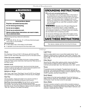
... Mode. 3 Do not use an extension cord. Do not use an adapter. If the power supply cord is too short, have a qualified electrician or serviceman install an outlet near the microwave oven. Touch and hold the Cancel control for about 3 seconds until 2 tones sound and padlock icon appears in death, fire... adjusted. Filter Reset Reset the filter status after 30 minutes). Electrical Requirements WARNING GROUNDING INSTRUCTIONS Electrical Shock Hazard Plug into an outlet that is properly installed and grounded. Do not remove ground prong.
... Mode. 3 Do not use an extension cord. Do not use an adapter. If the power supply cord is too short, have a qualified electrician or serviceman install an outlet near the microwave oven. Touch and hold the Cancel control for about 3 seconds until 2 tones sound and padlock icon appears in death, fire... adjusted. Filter Reset Reset the filter status after 30 minutes). Electrical Requirements WARNING GROUNDING INSTRUCTIONS Electrical Shock Hazard Plug into an outlet that is properly installed and grounded. Do not remove ground prong.
Use & Care Guide
Page 5
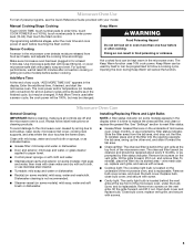
... uses 10% cook power. Microwave Oven Care General Cleaning IMPORTANT: Before cleaning, make sure all non-sensor cycles will be changed . Dishwasher cleaning is replaceable. Installing/Replacing Filters and Light Bulbs NOTE: A filter status indicator (on some models): mild soap, water and soft brush or dishwasher. To reinstall, place end of...
... uses 10% cook power. Microwave Oven Care General Cleaning IMPORTANT: Before cleaning, make sure all non-sensor cycles will be changed . Dishwasher cleaning is replaceable. Installing/Replacing Filters and Light Bulbs NOTE: A filter status indicator (on some models): mild soap, water and soft brush or dishwasher. To reinstall, place end of...
Use & Care Guide
Page 7
...defects in materials or workmanship and is reported to KitchenAid within 30 days from the date of purchase. 6. Damage resulting from accident, alteration, misuse, abuse, fire, flood, acts of God, improper installation, installation not in accordance with electrical or plumbing codes, or.../serial numbers that is contrary to published user or operator instructions and/or installation instructions. 4. Service calls to obtain service under these excluded circumstances shall be provided by a KitchenAid designated service company. Cosmetic damage, including scratches, dents, chips or other ...
...defects in materials or workmanship and is reported to KitchenAid within 30 days from the date of purchase. 6. Damage resulting from accident, alteration, misuse, abuse, fire, flood, acts of God, improper installation, installation not in accordance with electrical or plumbing codes, or.../serial numbers that is contrary to published user or operator instructions and/or installation instructions. 4. Service calls to obtain service under these excluded circumstances shall be provided by a KitchenAid designated service company. Cosmetic damage, including scratches, dents, chips or other ...


