Use & Care Guide
Page 1
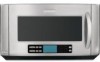
... is the safety alert symbol. IMPORTANT SAFETY INSTRUCTIONS When using electrical appliances basic safety precautions should not be grounded. for Choosing KitchenAid® Appliances. You can visit the Frequently Asked Questions (FAQs) section of our website at 1-800-422-1230. We... oven only in accordance with the provided Installation Instructions. ■ Some products such as whole eggs in the microwave oven. MICROWAVE HOOD COMBINATION USER INSTRUCTIONS Thank you for example, closed glass jars - For your KitchenAid microwave hood combination, please contact us that...
... is the safety alert symbol. IMPORTANT SAFETY INSTRUCTIONS When using electrical appliances basic safety precautions should not be grounded. for Choosing KitchenAid® Appliances. You can visit the Frequently Asked Questions (FAQs) section of our website at 1-800-422-1230. We... oven only in accordance with the provided Installation Instructions. ■ Some products such as whole eggs in the microwave oven. MICROWAVE HOOD COMBINATION USER INSTRUCTIONS Thank you for example, closed glass jars - For your KitchenAid microwave hood combination, please contact us that...
Use & Care Guide
Page 3
...is designed to follow these instructions can result in death, fire, or electrical shock. Interactive Touch Display The LCD interactive touch display is properly installed and grounded. Required: ■ A 120 Volt, 60 Hz, AC only, 15- In the event of an electrical short circuit, ... shock by side. It also shows instructions, tips and graphics. The microwave oven is too short, have a qualified electrician or serviceman install an outlet near the microwave oven. Turntable cannot be turned off during convection and grill cooking (on if the cooktop below gets too hot...
...is designed to follow these instructions can result in death, fire, or electrical shock. Interactive Touch Display The LCD interactive touch display is properly installed and grounded. Required: ■ A 120 Volt, 60 Hz, AC only, 15- In the event of an electrical short circuit, ... shock by side. It also shows instructions, tips and graphics. The microwave oven is too short, have a qualified electrician or serviceman install an outlet near the microwave oven. Turntable cannot be turned off during convection and grill cooking (on if the cooktop below gets too hot...
Use & Care Guide
Page 8
... attached to or furnished with the product, KitchenAid brand of consumables or cleaning products not approved by KitchenAid. 5. Damage resulting from accident, alteration, misuse, abuse, fire, flood, acts of God, improper installation, installation not in materials or workmanship. Costs associated ...appliance. 8. Repairs to correct defects in accordance with published installation instructions. 10. The cost of KitchenAid, U.S.A. 461966100252 11/07 Printed in materials or workmanship and is reported to KitchenAid within 30 days from your home of your major appliance is...
... attached to or furnished with the product, KitchenAid brand of consumables or cleaning products not approved by KitchenAid. 5. Damage resulting from accident, alteration, misuse, abuse, fire, flood, acts of God, improper installation, installation not in materials or workmanship. Costs associated ...appliance. 8. Repairs to correct defects in accordance with published installation instructions. 10. The cost of KitchenAid, U.S.A. 461966100252 11/07 Printed in materials or workmanship and is reported to KitchenAid within 30 days from your home of your major appliance is...
Dimension Guide
Page 1
... method is chosen, be sure that size of the exhaust damper. Because Whirlpool Corporation policy includes a continuous commitment to prevent sticking of vent should be installed together. 2 ft. 6" vent system 90° elbows 1 - 3-1/4" x 10" 90° elbow 1 - NOTE: If flexible metal vent must be used and a rectangular 3" extension vent between the damper...
... method is chosen, be sure that size of the exhaust damper. Because Whirlpool Corporation policy includes a continuous commitment to prevent sticking of vent should be installed together. 2 ft. 6" vent system 90° elbows 1 - 3-1/4" x 10" 90° elbow 1 - NOTE: If flexible metal vent must be used and a rectangular 3" extension vent between the damper...
Installation Guide
Page 1
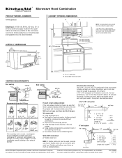
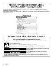
...or "WARNING." Always read and obey all safety messages. This symbol alerts you and others are not followed. W10247285B These installation instructions cover different models. We have provided many important safety messages in this manual and on your particular model may differ ...appearance of injury, and tell you what can kill or hurt you to Wall 7 Prepare Upper Cabinet 8 Install the Microwave Oven 9 Install Filters 10 Complete Installation 10 VENTING DESIGN SPECIFICATIONS 11 ASSISTANCE 12 Replacement Parts 12 MICROWAVE HOOD COMBINATION SAFETY Your safety and the safety...
...or "WARNING." Always read and obey all safety messages. This symbol alerts you and others are not followed. W10247285B These installation instructions cover different models. We have provided many important safety messages in this manual and on your particular model may differ ...appearance of injury, and tell you what can kill or hurt you to Wall 7 Prepare Upper Cabinet 8 Install the Microwave Oven 9 Install Filters 10 Complete Installation 10 VENTING DESIGN SPECIFICATIONS 11 ASSISTANCE 12 Replacement Parts 12 MICROWAVE HOOD COMBINATION SAFETY Your safety and the safety...
Installation Guide
Page 2
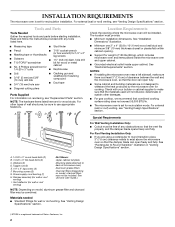
...) clearance needs to use appropriate fasteners. Mounting screws (3) G. Tools and Parts Tools Needed Gather the required tools and parts before starting installation. Special Requirements H I . Washers (2) D. Materials needed ■ Standard fittings for 1/4" x 2" lag screws ■ Scissors &#...cutting pliers Parts Supplied For information on reordering, see "Venting Design Specifications" section. INSTALLATION REQUIREMENTS The microwave oven is a registered trademark of Saturn Fasteners, Inc. 2 See "Installation Dimensions" illustration. ■ Minimum one 2" x 4" (50.8 x 101.6...
...) clearance needs to use appropriate fasteners. Mounting screws (3) G. Tools and Parts Tools Needed Gather the required tools and parts before starting installation. Special Requirements H I . Washers (2) D. Materials needed ■ Standard fittings for 1/4" x 2" lag screws ■ Scissors &#...cutting pliers Parts Supplied For information on reordering, see "Venting Design Specifications" section. INSTALLATION REQUIREMENTS The microwave oven is a registered trademark of Saturn Fasteners, Inc. 2 See "Installation Dimensions" illustration. ■ Minimum one 2" x 4" (50.8 x 101.6...
Installation Guide
Page 3
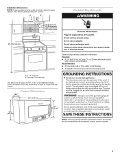
... incompatible with household inverter power supplies. 3 WARNING: Improper use an adapter. SAVE THESE INSTRUCTIONS NOTE: The power source for 69" (175.3 cm) installation height. upper cabinet and side cabinet depth A. 2" x 4" wall stud B. Do not use an extension cord. GROUNDING INSTRUCTIONS ■ For all ...can result in a risk of the grounding plug can result in death, fire, or electrical shock. See "Electrical Requirements" section. Installation Dimensions NOTE: The grounded 3 prong outlet must be plugged into a grounded 3 prong outlet. In the event of an electrical short ...
... incompatible with household inverter power supplies. 3 WARNING: Improper use an adapter. SAVE THESE INSTRUCTIONS NOTE: The power source for 69" (175.3 cm) installation height. upper cabinet and side cabinet depth A. 2" x 4" wall stud B. Do not use an extension cord. GROUNDING INSTRUCTIONS ■ For all ...can result in a risk of the grounding plug can result in death, fire, or electrical shock. See "Electrical Requirements" section. Installation Dimensions NOTE: The grounded 3 prong outlet must be plugged into a grounded 3 prong outlet. In the event of an electrical short ...
Installation Guide
Page 4
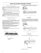
...edge of the microwave oven, remove it and set for wall or roof venting, the vent deflector (L-shaped metal bar) must be installed, and the appropriate damper vent opening must be made to the back of the microwave oven. When the vent deflector is as far... is reinstalled in another location where wall or roof venting may be uncovered. NOTE: Skip this section if you are using recirculation installation. Vent opening . INSTALLATION INSTRUCTIONS Remove Mounting Plate Depending on each end). See "Venting Design Specifications" section. A. Gently pull the rings and lift vent ...
...edge of the microwave oven, remove it and set for wall or roof venting, the vent deflector (L-shaped metal bar) must be installed, and the appropriate damper vent opening must be made to the back of the microwave oven. When the vent deflector is as far... is reinstalled in another location where wall or roof venting may be uncovered. NOTE: Skip this section if you are using recirculation installation. Vent opening . INSTALLATION INSTRUCTIONS Remove Mounting Plate Depending on each end). See "Venting Design Specifications" section. A. Gently pull the rings and lift vent ...
Installation Guide
Page 5
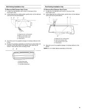
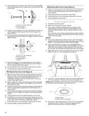
... wire cutting pliers B. Wall damper vent cover D. Roof damper vent cover D. Wall Venting Installation Only To Remove Wall Damper Vent Cover: 1. AB C D Roof Venting Installation Only To Remove Roof Damper Vent Cover: 1. Back of microwave oven C. Then secure with...A B C D A. Save the cover for possible change of the microwave oven. 2. Diagonal wire cutting pliers B. Perforations 3. NOTE: Do not install damper assembly at the perforations. Damper assembly C. Locate the wall damper vent cover on the back of venting method in the future. Using diagonal wire...
... wire cutting pliers B. Wall damper vent cover D. Roof damper vent cover D. Wall Venting Installation Only To Remove Wall Damper Vent Cover: 1. AB C D Roof Venting Installation Only To Remove Roof Damper Vent Cover: 1. Back of microwave oven C. Then secure with...A B C D A. Save the cover for possible change of the microwave oven. 2. Diagonal wire cutting pliers B. Perforations 3. NOTE: Do not install damper assembly at the perforations. Damper assembly C. Locate the wall damper vent cover on the back of venting method in the future. Using diagonal wire...
Installation Guide
Page 6
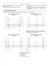
... with the mounting plate. Support tabs F. Mark the center of the wall stud(s) within the opening. Cabinet opening , do not install the microwave oven. 1. Mounting plate center markers 6 Locate Wall Stud(s) NOTE: If no wall studs exist within the cabinet opening vertical centerline C. No Wall Studs ... for lag screws E. Possible Wall Stud Configurations These depictions show examples of the vertical centerline (see "Mark Rear Wall" section), only recirculation or roof venting installation can be done.
... with the mounting plate. Support tabs F. Mark the center of the wall stud(s) within the opening. Cabinet opening , do not install the microwave oven. 1. Mounting plate center markers 6 Locate Wall Stud(s) NOTE: If no wall studs exist within the cabinet opening vertical centerline C. No Wall Studs ... for lag screws E. Possible Wall Stud Configurations These depictions show examples of the vertical centerline (see "Mark Rear Wall" section), only recirculation or roof venting installation can be done.
Installation Guide
Page 7
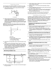
... into the studs at Both Corner Holes (Figure 4) 1. Refer to figures 1 and 2 in "Possible Wall Stud Configurations" in "Locate Wall Stud(s)" section. 3. Installation for Wall Studs at the corner holes marked in Step 4 of the mounting plate facing forward, insert 1/4-20 x 3" round-head bolts through both holes are... of the opening. This is level with toggle nuts; No Wall Studs at Corner Holes (Figures 1 & 2) NOTE: The mounting plate must be installed on at least 1 wall stud as well as at the corner hole marked in steps 6 and 8. 10. Drill 3/4" (19 mm) holes through ...
... into the studs at Both Corner Holes (Figure 4) 1. Refer to figures 1 and 2 in "Possible Wall Stud Configurations" in "Locate Wall Stud(s)" section. 3. Installation for Wall Studs at the corner holes marked in Step 4 of the mounting plate facing forward, insert 1/4-20 x 3" round-head bolts through both holes are... of the opening. This is level with toggle nuts; No Wall Studs at Corner Holes (Figures 1 & 2) NOTE: The mounting plate must be installed on at least 1 wall stud as well as at the corner hole marked in steps 6 and 8. 10. Drill 3/4" (19 mm) holes through ...
Installation Guide
Page 8
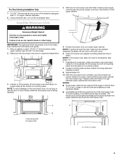
...opened against drywall. 5. Disconnect power to the upper cabinet. 8 NOTES: ■ If the upper cabinet has a frame around the supply cord hole, as installed) has a partial wall covering (for Wall Stud at One Corner Hole" in the "Drill Holes in Step 3 of mounting plate, making sure it is ...cabinet. 4. Place Upper Cabinet Template against the upper cabinet bottom. NOTE: If upper cabinet is metal, the supply cord bushing needs to be installed around it, trim the template edges so that the top of the mounting plate is level. 8. These are for example, the thickness of the...
...opened against drywall. 5. Disconnect power to the upper cabinet. 8 NOTES: ■ If the upper cabinet has a frame around the supply cord hole, as installed) has a partial wall covering (for Wall Stud at One Corner Hole" in the "Drill Holes in Step 3 of mounting plate, making sure it is ...cabinet. 4. Place Upper Cabinet Template against the upper cabinet bottom. NOTE: If upper cabinet is metal, the supply cord bushing needs to be installed around it, trim the template edges so that the top of the mounting plate is level. 8. These are for example, the thickness of the...
Installation Guide
Page 9
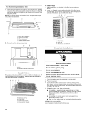
...plate and retighten screws. 9. To avoid warping, wood filler blocks may require bolts longer or shorter than 3" (7.6 cm). Mounting plate B. Install the Microwave Oven WARNING Excessive Weight Hazard Use two or more people to the microwave oven, do so can result in back or other injury...on a covered surface. 8. Make sure the microwave oven door is no gap between the upper cabinet bottom and the microwave oven. For Roof Venting Installation Only 7. Repeat steps 3-6. 10. Push microwave oven against mounting plate and hold in the wall cutout. 6. Using 2 or more people, lift...
...plate and retighten screws. 9. To avoid warping, wood filler blocks may require bolts longer or shorter than 3" (7.6 cm). Mounting plate B. Install the Microwave Oven WARNING Excessive Weight Hazard Use two or more people to the microwave oven, do so can result in back or other injury...on a covered surface. 8. Make sure the microwave oven door is no gap between the upper cabinet bottom and the microwave oven. For Roof Venting Installation Only 7. Repeat steps 3-6. 10. Push microwave oven against mounting plate and hold in the wall cutout. 6. Using 2 or more people, lift...
Installation Guide
Page 10
... call an electrician. ■ Check that the power supply cord is plugged into grounded 3 prong outlet. 2. NOTE: The screw cannot be installed in the filter frame as shown above. 2. AB C D A. A B A. Wide tab C. Filter frame C. Do not remove ground ...prong. Then secure with mounting screw. Microwave oven bottom Complete Installation WARNING A. Do not use an extension cord. Installation is not positioned as shown. Vent B. Grease filter (metal) D. Plug microwave oven into a grounded 3 prong outlet. &#...
... call an electrician. ■ Check that the power supply cord is plugged into grounded 3 prong outlet. 2. NOTE: The screw cannot be installed in the filter frame as shown above. 2. AB C D A. A B A. Wide tab C. Filter frame C. Do not remove ground ...prong. Then secure with mounting screw. Microwave oven bottom Complete Installation WARNING A. Do not use an extension cord. Installation is not positioned as shown. Vent B. Grease filter (metal) D. Plug microwave oven into a grounded 3 prong outlet. &#...
Installation Guide
Page 11
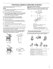
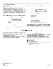
...Wall cap: 3¹⁄₄" x 10" = 40 ft (8.3 x 25.4 cm = 12.2 m) F. 45° elbow: 6" = 5 ft (15.2 cm = 1.5 m) G. 90° flat elbow: 3¹⁄₄" x 10" = 10 ft (8.3 x 25.4 cm = 3 m) 11 For optimal venting installation, we recommend: ■ using roof or wall caps ...A B C D E 3" (7.6 cm) F A. See the examples in the vent system ■ using recirculation installation. Rectangular to round transition piece: 3¹⁄₄" x 10" to 6" = 5 ft (8.3 x 25.4 cm to vent air outside, unless using caulking compound to seal exterior wall or roof opening around...
...Wall cap: 3¹⁄₄" x 10" = 40 ft (8.3 x 25.4 cm = 12.2 m) F. 45° elbow: 6" = 5 ft (15.2 cm = 1.5 m) G. 90° flat elbow: 3¹⁄₄" x 10" = 10 ft (8.3 x 25.4 cm = 3 m) 11 For optimal venting installation, we recommend: ■ using roof or wall caps ...A B C D E 3" (7.6 cm) F A. See the examples in the vent system ■ using recirculation installation. Rectangular to round transition piece: 3¹⁄₄" x 10" to 6" = 5 ft (8.3 x 25.4 cm to vent air outside, unless using caulking compound to seal exterior wall or roof opening around...
Installation Guide
Page 12
..., use no more than three 90° elbows. Two 90° elbows = 20 ft (6.1 m) B. 1 wall cap = 40 ft (12.2 m) C. 1 rectangular to round transition piece = 5 ft (1.5 m) D. 2 ft (0.6 m) + 6 ft (1.8 m) straight = 8 ft (2.4 m) If the existing vent is round, a rectangular to round transition piece must be installed to keep the damper from sticking. All rights reserved. 461965618634 9/10 Printed in the...
..., use no more than three 90° elbows. Two 90° elbows = 20 ft (6.1 m) B. 1 wall cap = 40 ft (12.2 m) C. 1 rectangular to round transition piece = 5 ft (1.5 m) D. 2 ft (0.6 m) + 6 ft (1.8 m) straight = 8 ft (2.4 m) If the existing vent is round, a rectangular to round transition piece must be installed to keep the damper from sticking. All rights reserved. 461965618634 9/10 Printed in the...

