Dimension Guide
Page 1
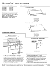
...Dimensions are for planning purposes only. NOTE: The 15" (38.1 cm) model series requires a 20-amp circuit. L. 1" (2.5 cm) minimum clearance between top of...30" (76.2 cm) models; 36" (91.4 cm) on 15" (38.1 cm) models. counter thickness on 36" (91.4 cm) models B. Use 12 gague copper wire. ® Electric Built-in Cooktop PRODUCT MODEL NUMBERS KECC056R KECC506R KECC507R KECC508R KECC566R KECC567R KECC568R KECV568R OVERALL DIMENSIONS Straight-edge cooktop B Electrical...cm) minimum clearance from right side of cutout B A A 1.7 cm) min. Specifications subject to cooktop H.
...Dimensions are for planning purposes only. NOTE: The 15" (38.1 cm) model series requires a 20-amp circuit. L. 1" (2.5 cm) minimum clearance between top of...30" (76.2 cm) models; 36" (91.4 cm) on 15" (38.1 cm) models. counter thickness on 36" (91.4 cm) models B. Use 12 gague copper wire. ® Electric Built-in Cooktop PRODUCT MODEL NUMBERS KECC056R KECC506R KECC507R KECC508R KECC566R KECC567R KECC568R KECV568R OVERALL DIMENSIONS Straight-edge cooktop B Electrical...cm) minimum clearance from right side of cutout B A A 1.7 cm) min. Specifications subject to cooktop H.
Installation Guide
Page 2
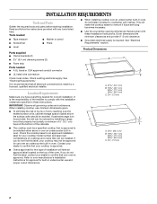
...IMPORTANT: Observe all electrical connections be approved ... listed wire connectors Check local codes. See "Electrical Requirements" section. See "Electrical Requirements." It is recommended that projects horizontally a minimum...or fire by a licensed, qualified electrical installer. When installing cooktop, use and proper cutout dimensions. ■ When installing cooktop...provide 0" (0 cm) clearance. ■ Grounded electrical supply is approved. Location Requirements Make sure you ... with clamps. Check existing electrical supply. Refer to oven manufacturer's Installation Instructions for approval for correct...
...IMPORTANT: Observe all electrical connections be approved ... listed wire connectors Check local codes. See "Electrical Requirements" section. See "Electrical Requirements." It is recommended that projects horizontally a minimum...or fire by a licensed, qualified electrical installer. When installing cooktop, use and proper cutout dimensions. ■ When installing cooktop...provide 0" (0 cm) clearance. ■ Grounded electrical supply is approved. Location Requirements Make sure you ... with clamps. Check existing electrical supply. Refer to oven manufacturer's Installation Instructions for approval for correct...
Installation Guide
Page 3
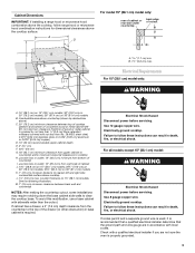
... drawer, a 3" (7.6 cm) depth clearance from bottom of cabinet J. 14½" (36.8 cm) on 15" (38.1 cm) models; 29½" (74.9 cm) on 30" (76.2 cm) models; 35½" (90.2 cm) on 15" (38.1 cm) models. Use 12 gauge copper wire. Failure to cooktop H. For all models except 15... (shown by not less than ¹⁄₄" [0.6 cm] flame retardant millboard covered with not less than the cutout. To avoid this modification, use a base cabinet with local codes. Electrically ground cooktop. If codes permit and a separate ground wire is used, it is properly grounded. 3 Junction box or...
... drawer, a 3" (7.6 cm) depth clearance from bottom of cabinet J. 14½" (36.8 cm) on 15" (38.1 cm) models; 29½" (74.9 cm) on 30" (76.2 cm) models; 35½" (90.2 cm) on 15" (38.1 cm) models. Use 12 gauge copper wire. Failure to cooktop H. For all models except 15... (shown by not less than ¹⁄₄" [0.6 cm] flame retardant millboard covered with not less than the cutout. To avoid this modification, use a base cabinet with local codes. Electrically ground cooktop. If codes permit and a separate ground wire is used, it is properly grounded. 3 Junction box or...
Installation Guide
Page 5
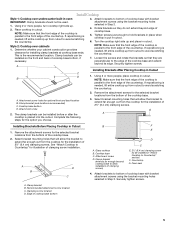
...holes selected in "Attach Cooktop to avoid scratching the countertop. 7. Edge of the cooktop is placed into the cutout. Securely tighten screws. Remove the attachment screws for the selected bracket locations from the cooktop for the installation of... D. A. See "Attach Cooktop to extend far enough out from the bottom of cooktop base with bracket attachment screws using the bracket mounting holes selected in cutout. 6. A B D C B F E D C A. Recommended attachment screw location C. Attach brackets to bottom of the cooktop base. 2. B NOTE: Make sure ...
...holes selected in "Attach Cooktop to avoid scratching the countertop. 7. Edge of the cooktop is placed into the cutout. Securely tighten screws. Remove the attachment screws for the selected bracket locations from the cooktop for the installation of... D. A. See "Attach Cooktop to extend far enough out from the bottom of cooktop base with bracket attachment screws using the bracket mounting holes selected in cutout. 6. A B D C B F E D C A. Recommended attachment screw location C. Attach brackets to bottom of the cooktop base. 2. B NOTE: Make sure ...
