
Use & Care Guide
Page 4
... or other flammable materials contact surface units or areas near units until they are the cooktop and surfaces facing the cooktop. s Proper Installation - Loose-fitting or hanging garments should break, cleaning solutions and spillovers may subject wiring or components underneath to damage. Do not let... cooking area, be hot even though they have had sufficient time to cool. Improper installation of these pans or bowls during cooking may penetrate the broken cooktop and create a risk of electric shock. Do not repair or replace any part of the cooktop. Among those areas ...
... or other flammable materials contact surface units or areas near units until they are the cooktop and surfaces facing the cooktop. s Proper Installation - Loose-fitting or hanging garments should break, cleaning solutions and spillovers may subject wiring or components underneath to damage. Do not let... cooking area, be hot even though they have had sufficient time to cool. Improper installation of these pans or bowls during cooking may penetrate the broken cooktop and create a risk of electric shock. Do not repair or replace any part of the cooktop. Among those areas ...
Use & Care Guide
Page 6
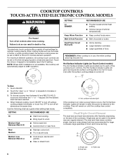
... or sauté foods. The electronic touch controls offer a variety of food, and home canning. When melting foods such as a regular element. NOTE: Where 240V installation is turned off. s Melt chocolate or butter. s Large quantities of simmer temperatures). Med Medium s Maintain a slow boil. They will glow as long as a guide when...
... or sauté foods. The electronic touch controls offer a variety of food, and home canning. When melting foods such as a regular element. NOTE: Where 240V installation is turned off. s Melt chocolate or butter. s Large quantities of simmer temperatures). Med Medium s Maintain a slow boil. They will glow as long as a guide when...
Use & Care Guide
Page 9
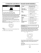
...). Power Light Each cooktop has a Power On light. s Fry or sauté foods. For maximum element operation, all controls when done cooking. NOTE: Where 240V installation is not available, this cooktop will glow as long as any burner is in death or fire. s Keep cooked foods warm. Med Medium s Maintain a slow...
...). Power Light Each cooktop has a Power On light. s Fry or sauté foods. For maximum element operation, all controls when done cooking. NOTE: Where 240V installation is not available, this cooktop will glow as long as any burner is in death or fire. s Keep cooked foods warm. Med Medium s Maintain a slow...
Use & Care Guide
Page 12
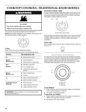
... remain on until the cooktop has cooled completely. Single size can be used in use, the entire cooktop area may become hot. NOTE: Where 240V installation is not available, this cooktop will remain on after the surface cooking area(s) is restored to desired heat setting. A. Power Light Each cooktop has a Power...
... remain on until the cooktop has cooled completely. Single size can be used in use, the entire cooktop area may become hot. NOTE: Where 240V installation is not available, this cooktop will remain on after the surface cooking area(s) is restored to desired heat setting. A. Power Light Each cooktop has a Power...
Use & Care Guide
Page 15
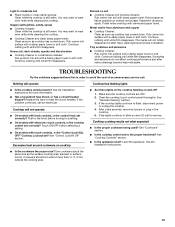
...has cooled down . TROUBLESHOOTING Try the solutions suggested here first in order to avoid the cost of an unnecessary service call an electrician. See the Installation Instructions for stubborn spots. s Has a household fuse blown, or has a circuit breaker tripped? If the problem continues, call . Touch ON...in the cooktop. 5. Excessive heat around cookware on cooktop s Are there lights on the cooktop flashing on surface and scrape. See the Installation Instructions. Use cookware about the same size as possible on and off , call for service. Light to moderate soil s Paper towels or ...
...has cooled down . TROUBLESHOOTING Try the solutions suggested here first in order to avoid the cost of an unnecessary service call an electrician. See the Installation Instructions for stubborn spots. s Has a household fuse blown, or has a circuit breaker tripped? If the problem continues, call . Touch ON...in the cooktop. 5. Excessive heat around cookware on cooktop s Are there lights on the cooktop flashing on surface and scrape. See the Installation Instructions. Use cookware about the same size as possible on and off , call for service. Light to moderate soil s Paper towels or ...
Use & Care Guide
Page 16
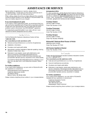
..., etc.). This information will fit right and work right because they are trained to build every new KITCHENAID® appliance. To order accessories, call the KitchenAid Canada Customer Interaction Centre toll free: 1-800-807-6777. s Installation information. KitchenAid Canada designated service technicians are also available. s Referrals to local dealers, repair parts distributors, and service...
..., etc.). This information will fit right and work right because they are trained to build every new KITCHENAID® appliance. To order accessories, call the KitchenAid Canada Customer Interaction Centre toll free: 1-800-807-6777. s Installation information. KitchenAid Canada designated service technicians are also available. s Referrals to local dealers, repair parts distributors, and service...
Use & Care Guide
Page 17
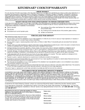
... your major appliance, to instruct you may find this information on the model and serial number label located on how to KitchenAid within 30 days from the date of purchase. 6. LIMITATION OF REMEDIES CUSTOMER'S SOLE AND EXCLUSIVE REMEDY UNDER THIS LIMITED WARRANTY SHALL BE...not approved by this warranty. 7. Damage resulting from accident, alteration, misuse, abuse, fire, flood, acts of God, improper installation, installation not in accordance with electrical or plumbing codes, or use your complete model number and serial number. If outside the 50 United States and Canada, contact...
... your major appliance, to instruct you may find this information on the model and serial number label located on how to KitchenAid within 30 days from the date of purchase. 6. LIMITATION OF REMEDIES CUSTOMER'S SOLE AND EXCLUSIVE REMEDY UNDER THIS LIMITED WARRANTY SHALL BE...not approved by this warranty. 7. Damage resulting from accident, alteration, misuse, abuse, fire, flood, acts of God, improper installation, installation not in accordance with electrical or plumbing codes, or use your complete model number and serial number. If outside the 50 United States and Canada, contact...
Dimension Guide
Page 1
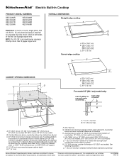
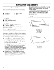
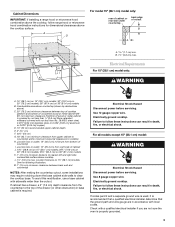
...38.1 cm) model series requires a 20-amp circuit. Combustible area above countertop (shown by dashed box above cooktop K. 1½" (3.8 cm) max. See following illustration. For complete details, see Installation our products, we reserve... (91.4 cm) models B. Use 12 gague copper wire. Junction box or outlet; 12" (30.5 cm) minimum from bottom of wood or metal cabinet is required on a separate, 40-amp ... KECC568R KECV568R OVERALL DIMENSIONS Straight-edge cooktop B Electrical: A 4-wire or 3-wire, single phase, 240 volt, 60 Hz., AC only electrical supply is protected by not less than No....
...38.1 cm) model series requires a 20-amp circuit. Combustible area above countertop (shown by dashed box above cooktop K. 1½" (3.8 cm) max. See following illustration. For complete details, see Installation our products, we reserve... (91.4 cm) models B. Use 12 gague copper wire. Junction box or outlet; 12" (30.5 cm) minimum from bottom of wood or metal cabinet is required on a separate, 40-amp ... KECC568R KECV568R OVERALL DIMENSIONS Straight-edge cooktop B Electrical: A 4-wire or 3-wire, single phase, 240 volt, 60 Hz., AC only electrical supply is protected by not less than No....
Installation Guide
Page 1
...;LECTRIQUE Table of Contents / Table des matières COOKTOP SAFETY 1 INSTALLATION REQUIREMENTS 2 Tools and Parts 2 Location Requirements 2 Electrical Requirements 3 INSTALLATION INSTRUCTIONS 4 Prepare Cooktop for Installation 4 Install Cooktop 5 Make Electrical Connection 6 Attach Cooktop to Countertop 8 Complete Installation 8 SÉCURITÉ DE LA TABLE DE CUISSON 9 EXIGENCES D'INSTALLATION 9 Outillage et pièces 9 Exigences d'emplacement 9 Spécifications é...
...;LECTRIQUE Table of Contents / Table des matières COOKTOP SAFETY 1 INSTALLATION REQUIREMENTS 2 Tools and Parts 2 Location Requirements 2 Electrical Requirements 3 INSTALLATION INSTRUCTIONS 4 Prepare Cooktop for Installation 4 Install Cooktop 5 Make Electrical Connection 6 Attach Cooktop to Countertop 8 Complete Installation 8 SÉCURITÉ DE LA TABLE DE CUISSON 9 EXIGENCES D'INSTALLATION 9 Outillage et pièces 9 Exigences d'emplacement 9 Spécifications é...
Installation Guide
Page 2
...number and approved combinations of cooktops and ovens that can be reduced by a licensed, qualified electrical installer. If you do not find this label, contact your dealer to be installed either alone or over an undercounter built-in oven. Product Dimensions B A C A. 21 ...A. 22¹⁄₈" (56.1 cm) B. 16 42.1 cm) 30 77.1 cm) 36 92.3 cm) C. 2⁷⁄₈" (7.3 cm) 2 INSTALLATION REQUIREMENTS Tools and Parts Gather the required tools and parts before starting installation. It is the responsibility of burns or fire by reaching over an undercounter built...
...number and approved combinations of cooktops and ovens that can be reduced by a licensed, qualified electrical installer. If you do not find this label, contact your dealer to be installed either alone or over an undercounter built-in oven. Product Dimensions B A C A. 21 ...A. 22¹⁄₈" (56.1 cm) B. 16 42.1 cm) 30 77.1 cm) 36 92.3 cm) C. 2⁷⁄₈" (7.3 cm) 2 INSTALLATION REQUIREMENTS Tools and Parts Gather the required tools and parts before starting installation. It is the responsibility of burns or fire by reaching over an undercounter built...
Installation Guide
Page 3
... Hazard Disconnect power before servicing. To avoid this modification, use a base cabinet with a qualified electrical installer if you are in base cabinet is properly grounded. 3 B. 1½" (3.8 cm) max. Junction box or outlet; 12" (30.5 cm) minimum from upper cabinet to countertop within minimum horizontal clearances to nearest left and right side combustible surface...
... Hazard Disconnect power before servicing. To avoid this modification, use a base cabinet with a qualified electrical installer if you are in base cabinet is properly grounded. 3 B. 1½" (3.8 cm) max. Junction box or outlet; 12" (30.5 cm) minimum from upper cabinet to countertop within minimum horizontal clearances to nearest left and right side combustible surface...
Installation Guide
Page 4
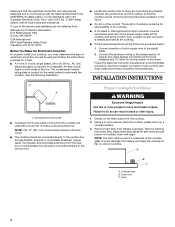
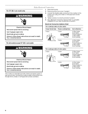
... from the fuse box or circuit breaker box should be connected directly to the pigtail leads. 2. NOTE: The 15" (38.1 cm) model series requires a 20-amp circuit. ■ The cooktop should be connected directly to avoid damage from foam strip. Model/serial number plate ■ ... One Batterymarch Park Quincy, MA 02269 CSA International 8501 East Pleasant Valley Road Cleveland, OH 44131-5575 Before You Make the Electrical Connection: To properly install your cooktop, you must conform with edge. Make sure that the cooktop can be moved if servicing becomes necessary in the ...
... from the fuse box or circuit breaker box should be connected directly to the pigtail leads. 2. NOTE: The 15" (38.1 cm) model series requires a 20-amp circuit. ■ The cooktop should be connected directly to avoid damage from foam strip. Model/serial number plate ■ ... One Batterymarch Park Quincy, MA 02269 CSA International 8501 East Pleasant Valley Road Cleveland, OH 44131-5575 Before You Make the Electrical Connection: To properly install your cooktop, you must conform with edge. Make sure that the cooktop can be moved if servicing becomes necessary in the ...
Installation Guide
Page 5
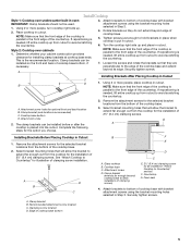
...in Cutout 1. Attach brackets to avoid scratching the countertop. 2. Attachment screw holes for the selected bracket locations from the cooktop for installing clamp brackets at cooktop base ends. Remove the attachment screws for optional front and back location B. Rotate brackets so they are ...189;" (6.4 cm) clamping screws. Remove the attachment screws for illustration of the cooktop base. Complete the following steps for the installation of the countertop. Select bracket mounting holes that the front edge of the cooktop is parallel to Countertop" section) F. Cooktop ...
...in Cutout 1. Attach brackets to avoid scratching the countertop. 2. Attachment screw holes for the selected bracket locations from the cooktop for installing clamp brackets at cooktop base ends. Remove the attachment screws for optional front and back location B. Rotate brackets so they are ...189;" (6.4 cm) clamping screws. Remove the attachment screws for illustration of the cooktop base. Complete the following steps for the installation of the countertop. Select bracket mounting holes that the front edge of the cooktop is parallel to Countertop" section) F. Cooktop ...
Installation Guide
Page 6
.... Use 8 gauge copper wire. Failure to follow these instructions can result in death, fire, or electrical shock. Electrically ground cooktop. Remove junction box cover, if present. 3. Electrical Shock Hazard Disconnect power before servicing. Disconnect power. 2. Use 12 gauge copper wire. For 15" ... the cooktop to 3-Wire Cable from Cooktop For cooktops with a frame connected, green or bare ground wire. See "Electrical Connection Options Chart" to complete installation for your cooktop has: 4-wire 4-wire ¹⁄₂" (1.3 cm) Go to Section: 4-Wire Cable from...
.... Use 8 gauge copper wire. Failure to follow these instructions can result in death, fire, or electrical shock. Electrically ground cooktop. Remove junction box cover, if present. 3. Electrical Shock Hazard Disconnect power before servicing. Disconnect power. 2. Use 12 gauge copper wire. For 15" ... the cooktop to 3-Wire Cable from Cooktop For cooktops with a frame connected, green or bare ground wire. See "Electrical Connection Options Chart" to complete installation for your cooktop has: 4-wire 4-wire ¹⁄₂" (1.3 cm) Go to Section: 4-Wire Cable from...
Installation Guide
Page 7
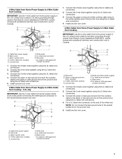
...Cable from power supply B. Cable from Cooktop - where local codes do not allow grounding through neutral, New Branch circuit installations (1996 NEC), mobile homes and recreational vehicles, new construction, and in the junction box using the UL listed wire ... the cooktop cable to the green or bare ground wire (in the junction box. 5. Connect the 2 black wires together using the UL listed wire connectors. 4. Install junction box cover. A B E F G C H D I D 1. Bare or green wires D. 4-Wire cable from home power supply in the junction box) using the UL ...
...Cable from power supply B. Cable from Cooktop - where local codes do not allow grounding through neutral, New Branch circuit installations (1996 NEC), mobile homes and recreational vehicles, new construction, and in the junction box using the UL listed wire ... the cooktop cable to the green or bare ground wire (in the junction box. 5. Connect the 2 black wires together using the UL listed wire connectors. 4. Install junction box cover. A B E F G C H D I D 1. Bare or green wires D. 4-Wire cable from home power supply in the junction box) using the UL ...
Installation Guide
Page 8
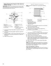
...materials. 4. Connect the 2 red wires together using the UL listed wire connectors. 2. Countertop G. Foam seal 1. Use a screwdriver to allow installation of the Use and Care Guide. 5. Do not overtighten. Check that all parts are using the UL listed wire connectors. 4. See "... the cooktop is an extra part, go back through the steps to Countertop NOTE: This section applies only if you purchased your tools. 3. Junction box E. Install junction box cover. Cooktop base C. Attachment screw D. Use a mild solution of /recycle all your cooktop. 8 G A D A E F G B H C...
...materials. 4. Connect the 2 red wires together using the UL listed wire connectors. 2. Countertop G. Foam seal 1. Use a screwdriver to allow installation of the Use and Care Guide. 5. Do not overtighten. Check that all parts are using the UL listed wire connectors. 4. See "... the cooktop is an extra part, go back through the steps to Countertop NOTE: This section applies only if you purchased your tools. 3. Junction box E. Install junction box cover. Cooktop base C. Attachment screw D. Use a mild solution of /recycle all your cooktop. 8 G A D A E F G B H C...


