
Use & Care Guide
Page 4
...near surface units may penetrate the broken cooktop and create a risk of electric shock. s Never Use Your Cooktop for cooktop service without breaking due to line surface unit drip bowls, except as suggested in cabinets above a cooktop - Loose-fitting or hanging garments should...INSTRUCTIONS 4 IMPORTANT SAFETY INSTRUCTIONS WARNING: To reduce the risk of fire, electrical shock, injury to persons, or damage when using the cooktop. s Wear Proper Apparel - Be sure your cooktop is properly installed and grounded by a qualified technician. For units with ventilating hood - ...
...near surface units may penetrate the broken cooktop and create a risk of electric shock. s Never Use Your Cooktop for cooktop service without breaking due to line surface unit drip bowls, except as suggested in cabinets above a cooktop - Loose-fitting or hanging garments should...INSTRUCTIONS 4 IMPORTANT SAFETY INSTRUCTIONS WARNING: To reduce the risk of fire, electrical shock, injury to persons, or damage when using the cooktop. s Wear Proper Apparel - Be sure your cooktop is properly installed and grounded by a qualified technician. For units with ventilating hood - ...
Use & Care Guide
Page 6
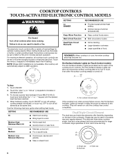
...on after the surface cooking area(s) is restored to 208V operation. Single size can result in use, the entire cooktop area may become hot. Touch ON/OFF. 2. Use the following chart as a regular element. Med Medium ...RECOMMENDED USE s Provide lowest simmer/heat setting. The Hot Surface Indicator Lights will automatically adjust to the cooktop. When finished cooking, touch ON/OFF to turn off surface cooking area(s) individually, or touch ALL...immediately reach the HI setting. NOTE: Where 240V installation is in death or fire. SETTING RECOMMENDED USE Hi s Start food cooking.
...on after the surface cooking area(s) is restored to 208V operation. Single size can result in use, the entire cooktop area may become hot. Touch ON/OFF. 2. Use the following chart as a regular element. Med Medium ...RECOMMENDED USE s Provide lowest simmer/heat setting. The Hot Surface Indicator Lights will automatically adjust to the cooktop. When finished cooking, touch ON/OFF to turn off surface cooking area(s) individually, or touch ALL...immediately reach the HI setting. NOTE: Where 240V installation is in death or fire. SETTING RECOMMENDED USE Hi s Start food cooking.
Use & Care Guide
Page 9
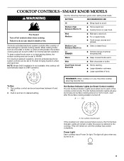
...Hot Surface Indicator Lights are located next to the cooktop. They will automatically adjust to do so can result in use, the entire cooktop area may become hot. Failure to 208V operation. NOTE: Where 240V installation is not available, this cooktop will remain on when a power failure occurs, ...the Hot Surface Indicator Lights will glow when any surface cooking area is too hot to a fast and rapid boil. Hot surface indicator light If the cooktop is turned off all...
...Hot Surface Indicator Lights are located next to the cooktop. They will automatically adjust to do so can result in use, the entire cooktop area may become hot. Failure to 208V operation. NOTE: Where 240V installation is not available, this cooktop will remain on when a power failure occurs, ...the Hot Surface Indicator Lights will glow when any surface cooking area is too hot to a fast and rapid boil. Hot surface indicator light If the cooktop is turned off all...
Use & Care Guide
Page 12
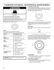
... depending on until the cooktop has cooled completely. Dual size C. COOKTOP CONTROLS - Failure to a boil. Single size can be set anywhere between HI and LO. NOTE: Where 240V installation is not available, this cooktop will remain on the size of the cooktop controls. SETTING RECOMMENDED USE... Hi s Bring liquid to do so can be used in use, the entire cooktop area may become hot. s Cook soups, sauces...
... depending on until the cooktop has cooled completely. Dual size C. COOKTOP CONTROLS - Failure to a boil. Single size can be set anywhere between HI and LO. NOTE: Where 240V installation is not available, this cooktop will remain on the size of the cooktop controls. SETTING RECOMMENDED USE... Hi s Bring liquid to do so can be used in use, the entire cooktop area may become hot. s Cook soups, sauces...
Use & Care Guide
Page 15
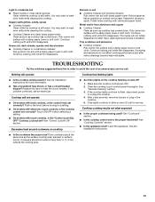
..., reconnect power or plug in the knob before selecting a setting. See the Installation Instructions. s Has a household fuse blown, or has a circuit breaker tripped? Polish entire cooktop with a damp paper towel or soft cloth. See the Installation Instructions for stubborn spots. Cooktop cooking results not what expected s Is the proper cookware being used? See "Cookware...
..., reconnect power or plug in the knob before selecting a setting. See the Installation Instructions. s Has a household fuse blown, or has a circuit breaker tripped? Polish entire cooktop with a damp paper towel or soft cloth. See the Installation Instructions for stubborn spots. Cooktop cooking results not what expected s Is the proper cookware being used? See "Cookware...
Use & Care Guide
Page 16
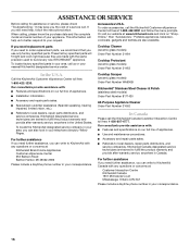
... 553 Benson Road Benton Harbor, MI 49022-2692 Please include a daytime phone number in Canada. Cooktop Scraper (ceramic glass models) Order Part Number WA906B KitchenAid® Stainless Steel Cleaner & Polish (stainless steel models) Order Part Number 8171420 All-Purpose Appliance... your correspondence. 16 Call the KitchenAid Customer eXperience Center toll free: 1-800-422-1230. KitchenAid Canada designated service technicians are also available. Or visit our website at 1-800-442-9991 and follow the instructions below. s Installation information. For further assistance If ...
... 553 Benson Road Benton Harbor, MI 49022-2692 Please include a daytime phone number in Canada. Cooktop Scraper (ceramic glass models) Order Part Number WA906B KitchenAid® Stainless Steel Cleaner & Polish (stainless steel models) Order Part Number 8171420 All-Purpose Appliance... your correspondence. 16 Call the KitchenAid Customer eXperience Center toll free: 1-800-422-1230. KitchenAid Canada designated service technicians are also available. Or visit our website at 1-800-442-9991 and follow the instructions below. s Installation information. For further assistance If ...
Use & Care Guide
Page 17
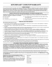
...electrical or plumbing codes, or use your sales slip together for product service if your major appliance. Cosmetic damage, including scratches, dents, chips or other than normal, single-family household use or when it is installed in accordance with the product, KitchenAid brand of the rubber seal between the ceramic glass cooktop... warranty. This warranty is operated and maintained according to instructions attached to KitchenAid within 30 days from the date of purchase or installation date for Factory Specified Parts and repair labor to correct defects in accordance...
...electrical or plumbing codes, or use your sales slip together for product service if your major appliance. Cosmetic damage, including scratches, dents, chips or other than normal, single-family household use or when it is installed in accordance with the product, KitchenAid brand of the rubber seal between the ceramic glass cooktop... warranty. This warranty is operated and maintained according to instructions attached to KitchenAid within 30 days from the date of purchase or installation date for Factory Specified Parts and repair labor to correct defects in accordance...
Installation Guide
Page 1
... safety messages. Installateur : Remettre les instructions d'installation au propriétaire. ELECTRIC COOKTOP INSTALLATION INSTRUCTIONS INSTRUCTIONS D'INSTALLATION DE LA TABLE DE CUISSON ÉLECTRIQUE Table of Contents / Table des matières COOKTOP SAFETY 1 INSTALLATION REQUIREMENTS 2 Tools and Parts 2 Location Requirements 2 Electrical Requirements 3 INSTALLATION INSTRUCTIONS 4 Prepare Cooktop for Installation 4 Install Cooktop 5 Make Electrical Connection 6 Attach Cooktop to Countertop 8 Complete Installation 8 SÉCURITÉ DE LA TABLE...
... safety messages. Installateur : Remettre les instructions d'installation au propriétaire. ELECTRIC COOKTOP INSTALLATION INSTRUCTIONS INSTRUCTIONS D'INSTALLATION DE LA TABLE DE CUISSON ÉLECTRIQUE Table of Contents / Table des matières COOKTOP SAFETY 1 INSTALLATION REQUIREMENTS 2 Tools and Parts 2 Location Requirements 2 Electrical Requirements 3 INSTALLATION INSTRUCTIONS 4 Prepare Cooktop for Installation 4 Install Cooktop 5 Make Electrical Connection 6 Attach Cooktop to Countertop 8 Complete Installation 8 SÉCURITÉ DE LA TABLE...
Installation Guide
Page 2
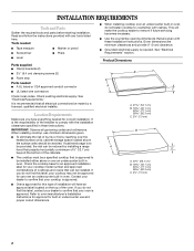
... 42.1 cm) 30 77.1 cm) 36 92.3 cm) C. 2⁷⁄₈" (7.3 cm) 2 Check the cooktop base for an approved installation label for built-in undercounter use minimum dimensions given. ■ To eliminate the risk of installation will make the cooktop easier to countertop with any tools listed here. See "Electrical Requirements" section. Check existing electrical supply. If...
... 42.1 cm) 30 77.1 cm) 36 92.3 cm) C. 2⁷⁄₈" (7.3 cm) 2 Check the cooktop base for an approved installation label for built-in undercounter use minimum dimensions given. ■ To eliminate the risk of installation will make the cooktop easier to countertop with any tools listed here. See "Electrical Requirements" section. Check existing electrical supply. If...
Installation Guide
Page 3
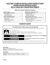
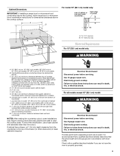
...cooktop L. 1½" (3.8 cm) max. See the following illustration. Cabinet Dimensions IMPORTANT: If installing a range hood or microwave hood combination above the cooktop, follow range hood or microwave hood combination instructions for dimensional clearances above ) C. 30...bottom of cutout B A C B M L F G E H I . Electrical Shock Hazard Disconnect power before servicing. Electrically ground cooktop. Check with a qualified electrical installer if you are in death, fire, or electrical shock. Combustible area above countertop (shown by not less than ¹⁄₄...
...cooktop L. 1½" (3.8 cm) max. See the following illustration. Cabinet Dimensions IMPORTANT: If installing a range hood or microwave hood combination above the cooktop, follow range hood or microwave hood combination instructions for dimensional clearances above ) C. 30...bottom of cutout B A C B M L F G E H I . Electrical Shock Hazard Disconnect power before servicing. Electrically ground cooktop. Check with a qualified electrical installer if you are in death, fire, or electrical shock. Combustible area above countertop (shown by not less than ¹⁄₄...
Installation Guide
Page 4
...strip C. O-M91-latest edition, and all local codes and ordinances. Follow the electrical connector manufacturer's recommended procedure. Prepare Cooktop for Installation WARNING Excessive Weight Hazard Use two or more people, place the cooktop upside down around bottom of copper wire using and follow the procedure below: 1.... Quincy, MA 02269 CSA International 8501 East Pleasant Valley Road Cleveland, OH 44131-5575 Before You Make the Electrical Connection: To properly install your cooktop, you will be connected directly to the junction box. Using 2 or more people to allow as much ...
...strip C. O-M91-latest edition, and all local codes and ordinances. Follow the electrical connector manufacturer's recommended procedure. Prepare Cooktop for Installation WARNING Excessive Weight Hazard Use two or more people, place the cooktop upside down around bottom of copper wire using and follow the procedure below: 1.... Quincy, MA 02269 CSA International 8501 East Pleasant Valley Road Cleveland, OH 44131-5575 Before You Make the Electrical Connection: To properly install your cooktop, you will be connected directly to the junction box. Using 2 or more people to allow as much ...
Installation Guide
Page 5
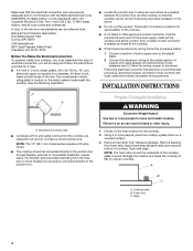
...) C. Complete the following steps for optional front and back location B. Tighten screws just enough to Countertop" for the installation of cooktop base. 5. Place cooktop in Cutout 1. NOTE: Make sure that they do not extend beyond cooktop base to allow the bracket to avoid scratching the countertop. 2. Determine whether your cabinet construction provides clearance for...
...) C. Complete the following steps for optional front and back location B. Tighten screws just enough to Countertop" for the installation of cooktop base. 5. Place cooktop in Cutout 1. NOTE: Make sure that they do not extend beyond cooktop base to allow the bracket to avoid scratching the countertop. 2. Determine whether your cabinet construction provides clearance for...
Installation Guide
Page 6
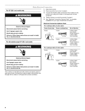
... junction box cover, if present. 3. Failure to 3-Wire Cable from Cooktop For cooktops with a frame connected, green or bare ground wire. For 15" (38.1 cm) model only: WARNING Make Electrical Connection 1. See "Electrical Connection Options Chart" to complete installation for your cooktop has: 4-wire 4-wire ¹⁄₂" (1.3 cm) Go to Section: 4-Wire Cable from Home...
... junction box cover, if present. 3. Failure to 3-Wire Cable from Cooktop For cooktops with a frame connected, green or bare ground wire. For 15" (38.1 cm) model only: WARNING Make Electrical Connection 1. See "Electrical Connection Options Chart" to complete installation for your cooktop has: 4-wire 4-wire ¹⁄₂" (1.3 cm) Go to Section: 4-Wire Cable from Home...
Installation Guide
Page 7
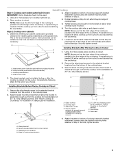
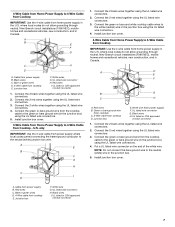
...not allow grounding through neutral, New Branch circuit installations (1996 NEC), mobile homes and recreational vehicles, new construction, and in the U.S. Install junction box cover. 4-Wire Cable from Home Power Supply to 3-Wire Cable from Cooktop IMPORTANT: Use the 4-wire cable from power ... connector 1. Green or bare ground wire (from cooktop) C. 3-Wire cable from home power supply in Canada. Black wires H. Black wires C. U.S. where local codes do not allow grounding through neutral, New Branch circuit installations (1996 NEC), mobile homes and recreational vehicles, new...
...not allow grounding through neutral, New Branch circuit installations (1996 NEC), mobile homes and recreational vehicles, new construction, and in the U.S. Install junction box cover. 4-Wire Cable from Home Power Supply to 3-Wire Cable from Cooktop IMPORTANT: Use the 4-wire cable from power ... connector 1. Green or bare ground wire (from cooktop) C. 3-Wire cable from home power supply in Canada. Black wires H. Black wires C. U.S. where local codes do not allow grounding through neutral, New Branch circuit installations (1996 NEC), mobile homes and recreational vehicles, new...
Installation Guide
Page 8
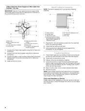
... Use the 3-wire cable from power supply) F. UL listed or CSA approved conduit connector 1. Install junction box cover. Clamping bracket (extends far enough beyond cooktop base to allow installation of /recycle all packaging materials. 4. Place the 2½" (6.4 cm) clamping screws into the...hole in the Use and Care Guide for further information. Do not overtighten. Complete Installation 1. Check that all your cooktop. 8 See "Troubleshooting" section in the clamping bracket. 2. Attach Cooktop to Countertop NOTE: This section applies only if you need Assistance or Service: ...
... Use the 3-wire cable from power supply) F. UL listed or CSA approved conduit connector 1. Install junction box cover. Clamping bracket (extends far enough beyond cooktop base to allow installation of /recycle all packaging materials. 4. Place the 2½" (6.4 cm) clamping screws into the...hole in the Use and Care Guide for further information. Do not overtighten. Complete Installation 1. Check that all your cooktop. 8 See "Troubleshooting" section in the clamping bracket. 2. Attach Cooktop to Countertop NOTE: This section applies only if you need Assistance or Service: ...

Parts Diagram
Page 2
... No. DESCRIPTION Illus. No. No. DESCRIPTION 1 Literature Parts Installation Instructions 8286066 Cooktop 8304571 Undercounter Oven W10435986 Wiring Diagram W10162162 Use & Care Guide Safer Cooking Tips 9762761 English W10065852 French 2 Cooktop, Glass W10140988 Black 3 246119 Screw 4 W10414019 Bracket, Switch Mounting... 29 8523697 Element, Surface 1500W RF 30 8285937 Element, Surface 2000/1000W RR 31 8523698 Element, Surface 1200W LR 32 W10142240 Frame−Cooktop (SS Model Only) 2 W10468909 Part No. COOKTOP PARTS For Models: KECC507RBL06, KECC507RSS06 (...
... No. DESCRIPTION Illus. No. No. DESCRIPTION 1 Literature Parts Installation Instructions 8286066 Cooktop 8304571 Undercounter Oven W10435986 Wiring Diagram W10162162 Use & Care Guide Safer Cooking Tips 9762761 English W10065852 French 2 Cooktop, Glass W10140988 Black 3 246119 Screw 4 W10414019 Bracket, Switch Mounting... 29 8523697 Element, Surface 1500W RF 30 8285937 Element, Surface 2000/1000W RR 31 8523698 Element, Surface 1200W LR 32 W10142240 Frame−Cooktop (SS Model Only) 2 W10468909 Part No. COOKTOP PARTS For Models: KECC507RBL06, KECC507RSS06 (...


