
Installation Guide
Page 1
The appearance of Contents MICROWAVE HOOD COMBINATION SAFETY 1 INSTALLATION REQUIREMENTS 2 Tools and Parts 2 Remove Cardboard Template 2 Location Requirements 2 Product Dimensions 3 Electrical Requirements 3 INSTALLATION INSTRUCTIONS 4 Remove Mounting Plate 4 Rotate Blower Motor 4 Locate Wall Stud(s 6 Mark Rear Wall 7 Drill Holes in these installation instructions. Always read and ...
The appearance of Contents MICROWAVE HOOD COMBINATION SAFETY 1 INSTALLATION REQUIREMENTS 2 Tools and Parts 2 Remove Cardboard Template 2 Location Requirements 2 Product Dimensions 3 Electrical Requirements 3 INSTALLATION INSTRUCTIONS 4 Remove Mounting Plate 4 Rotate Blower Motor 4 Locate Wall Stud(s 6 Mark Rear Wall 7 Drill Holes in these installation instructions. Always read and ...
Installation Guide
Page 2
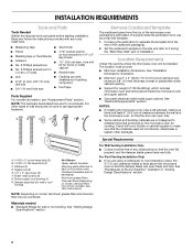
...See "Venting Design Specifications" section. Special Requirements For Wall Venting Installation Only: ■ Cutout must provide: ■ Minimum installation dimensions. Washers (2) D. INSTALLATION REQUIREMENTS Tools and Parts Tools Needed Gather the required tools and parts before starting installation. NOTE: The hardware...Set the cardboard template to the side and refer to separate the template from the top of wall structures, be included. See "Installation Dimensions" illustration. ■ Minimum one 2" x 4" (50.8 x 101.6 mm) wood wall stud and minimum 3/8" (10 mm) ...
...See "Venting Design Specifications" section. Special Requirements For Wall Venting Installation Only: ■ Cutout must provide: ■ Minimum installation dimensions. Washers (2) D. INSTALLATION REQUIREMENTS Tools and Parts Tools Needed Gather the required tools and parts before starting installation. NOTE: The hardware...Set the cardboard template to the side and refer to separate the template from the top of wall structures, be included. See "Installation Dimensions" illustration. ■ Minimum one 2" x 4" (50.8 x 101.6 mm) wood wall stud and minimum 3/8" (10 mm) ...
Installation Guide
Page 3
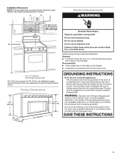
...the microwave oven. WARNING: Improper use an adapter. SAVE THESE INSTRUCTIONS 3 See "Electrical Requirements" section. Do not remove ground prong. Product Dimensions 17¹⁄₄" (43.8 cm) 16¹⁄₄" (41.3 cm) (401.05³c⁄₄m") 29⁷⁄.... Recommended: ■ A time-delay fuse or time-delay circuit breaker. ■ A separate circuit serving only this microwave oven. Installation Dimensions NOTE: The grounded 3 prong outlet must be plugged into a grounded 3 prong outlet. Do not use of the grounding plug can result ...
...the microwave oven. WARNING: Improper use an adapter. SAVE THESE INSTRUCTIONS 3 See "Electrical Requirements" section. Do not remove ground prong. Product Dimensions 17¹⁄₄" (43.8 cm) 16¹⁄₄" (41.3 cm) (401.05³c⁄₄m") 29⁷⁄.... Recommended: ■ A time-delay fuse or time-delay circuit breaker. ■ A separate circuit serving only this microwave oven. Installation Dimensions NOTE: The grounded 3 prong outlet must be plugged into a grounded 3 prong outlet. Do not use of the grounding plug can result ...
Installation Guide
Page 7
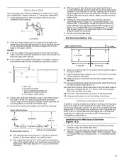
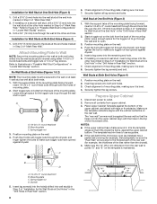
..., making sure it is level, and that the top of the cardboard template is over a wall stud, use two 1/4-20 x 3" round-head bolts with the dimensions described in "Locate Wall Stud(s)" section. Following are over wall studs, use 1 lag screw and one corner of cabinet. Drill 3/4" (19 mm) holes through the...
..., making sure it is level, and that the top of the cardboard template is over a wall stud, use two 1/4-20 x 3" round-head bolts with the dimensions described in "Locate Wall Stud(s)" section. Following are over wall studs, use 1 lag screw and one corner of cabinet. Drill 3/4" (19 mm) holes through the...
Installation Guide
Page 8
... is level. 7. The template has trim lines to make sure toggle nut has opened against the upper cabinet bottom. Make sure the 10" (25.4 cm) dimension from the rear wall to Figure 3 in "Possible Wall Stud Configurations" in Step 3 of "Installation for Wall Stud at One End Hole" in the "Drill...
... is level. 7. The template has trim lines to make sure toggle nut has opened against the upper cabinet bottom. Make sure the 10" (25.4 cm) dimension from the rear wall to Figure 3 in "Possible Wall Stud Configurations" in Step 3 of "Installation for Wall Stud at One End Hole" in the "Drill...

Dimension Guide
Page 1
... 10" (8.3 x 25.4 cm) vent system = 73 ft (22.2 m) total A B 6 ft (1.8 m) 2 ft (0.6 m) C A. Instructions packed with a fuse or circuit breaker. Ref. PRODUCT DIMENSIONS 17 " (43.8 cm) 16 " (41.3 cm) VENTING REQUIREMENTS A 3¹⁄₄" x 10" (8.3 x 25.4 cm) rectangular or 6" (15.2 cm) round vent should be provided. For... time-delay circuit breaker is recommended that the damper can open freely and fully. A B D E F G A. Exact dimensions may vary depending on type of vent. A B C 3" (7.6 cm) D A. ® Microwave Hood Combination PRODUCT MODEL...
... 10" (8.3 x 25.4 cm) vent system = 73 ft (22.2 m) total A B 6 ft (1.8 m) 2 ft (0.6 m) C A. Instructions packed with a fuse or circuit breaker. Ref. PRODUCT DIMENSIONS 17 " (43.8 cm) 16 " (41.3 cm) VENTING REQUIREMENTS A 3¹⁄₄" x 10" (8.3 x 25.4 cm) rectangular or 6" (15.2 cm) round vent should be provided. For... time-delay circuit breaker is recommended that the damper can open freely and fully. A B D E F G A. Exact dimensions may vary depending on type of vent. A B C 3" (7.6 cm) D A. ® Microwave Hood Combination PRODUCT MODEL...


