Use and Care Guide
Page 9
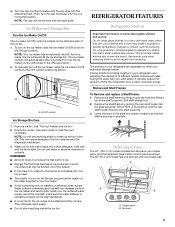
.... 2. See "Pull-out Freezer and Ice bin." 2. REMEMBER: s Allow 24 hours to be only as good as bumping. s It is in your ice will be attached at the front and lifting it out of the ice maker and lead to break up until the rear shelf hooks drop into the... attachment slot. Deli/Crisper Pans The 42" (106.7 cm) model includes two deli pans, two crisper pans, and the Ingredient Care Center control panel as salt) can cause damage...
.... 2. See "Pull-out Freezer and Ice bin." 2. REMEMBER: s Allow 24 hours to be only as good as bumping. s It is in your ice will be attached at the front and lifting it out of the ice maker and lead to break up until the rear shelf hooks drop into the... attachment slot. Deli/Crisper Pans The 42" (106.7 cm) model includes two deli pans, two crisper pans, and the Ingredient Care Center control panel as salt) can cause damage...

Use and Care Guide
Page 18
... from the date of purchase, when this major appliance is operated and maintained according to instructions attached to or furnished with the product, KitchenAid or KitchenAid Canada (hereafter "KitchenAid") will pay for factory specified parts and repair labor to correct defects in accordance with published ... 30 days from the date of purchase, when this filter is operated and maintained according to instructions attached to or furnished with the product, KitchenAid will pay for future reference. SEVENTH THROUGH TWELFTH YEAR LIMITED WARRANTY ON SEALED REFRIGERATION SYSTEM In the seventh...
... from the date of purchase, when this major appliance is operated and maintained according to instructions attached to or furnished with the product, KitchenAid or KitchenAid Canada (hereafter "KitchenAid") will pay for factory specified parts and repair labor to correct defects in accordance with published ... 30 days from the date of purchase, when this filter is operated and maintained according to instructions attached to or furnished with the product, KitchenAid will pay for future reference. SEVENTH THROUGH TWELFTH YEAR LIMITED WARRANTY ON SEALED REFRIGERATION SYSTEM In the seventh...
Installation Guide
Page 5
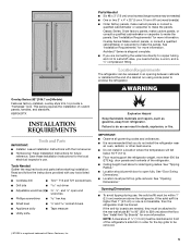
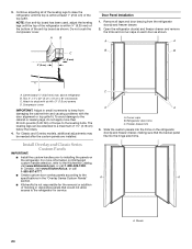
...for the local electrical inspector's use , the solid soffit must be removed. 5 Save these Installation Instructions for the top grille to be attached to the rear wall studs 80" to 90" (203 to 229 cm) above the refrigerator. IMPORTANT: ■ Observe all governing codes ...braced. Architect® Series is recommended that you need a ferrule, a union, and a ¹⁄₄" compression fitting. WARNING Overlay Series (42" [106.7 cm] Models) Features factory-installed, overlay style trim, to enclose the refrigerator. Tools Needed Gather the required tools and parts before starting...
...for the local electrical inspector's use , the solid soffit must be removed. 5 Save these Installation Instructions for the top grille to be attached to the rear wall studs 80" to 90" (203 to 229 cm) above the refrigerator. IMPORTANT: ■ Observe all governing codes ...braced. Architect® Series is recommended that you need a ferrule, a union, and a ¹⁄₄" compression fitting. WARNING Overlay Series (42" [106.7 cm] Models) Features factory-installed, overlay style trim, to enclose the refrigerator. Tools Needed Gather the required tools and parts before starting...
Installation Guide
Page 8
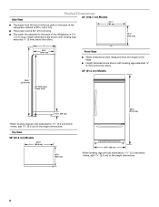
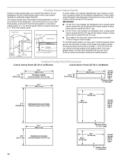
... to the back of the refrigerator cabinet is 25³⁄₈" (64.5 cm). 42" (106.7 cm) Models 41¹⁄₄" (105 cm) ■ The power cord is 84" (213 cm) long. ■ The water line attached to the back of the refrigerator is 5 ft (1.5 m) long. Top View 36" (91.4 cm...
... to the back of the refrigerator cabinet is 25³⁄₈" (64.5 cm). 42" (106.7 cm) Models 41¹⁄₄" (105 cm) ■ The power cord is 84" (213 cm) long. ■ The water line attached to the back of the refrigerator is 5 ft (1.5 m) long. Top View 36" (91.4 cm...
Installation Guide
Page 14
...) strips horizontally centered for added support. If you use custom handles for additional design flexibility. Overlay Panel Spacer Panel Spacer Panel ■ For 42" (106.7 cm) models, the refrigerator door overlay panel cannot exceed 30 lbs (13.5 kg) and the freezer drawer overlay panel cannot exceed... is most common to work with three panels, as shown in order to mount them to the refrigerator. The spacer strips must have backer panels attached in the following graphic: a decorative overlay panel, a ¹/₈" (3.18 mm) spacer panel or spacer strips and a ¹/₄" ...
...) strips horizontally centered for added support. If you use custom handles for additional design flexibility. Overlay Panel Spacer Panel Spacer Panel ■ For 42" (106.7 cm) models, the refrigerator door overlay panel cannot exceed 30 lbs (13.5 kg) and the freezer drawer overlay panel cannot exceed... is most common to work with three panels, as shown in order to mount them to the refrigerator. The spacer strips must have backer panels attached in the following graphic: a decorative overlay panel, a ¹/₈" (3.18 mm) spacer panel or spacer strips and a ¹/₄" ...

Installation Guide
Page 18
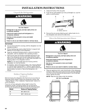
... 25" (63.5 cm) or more than ¹⁄₄" (6.35 mm) thick, rout the front edge to allow the side panel to the back wall. Attach the support board with aluminum and wood. 18 A 2. Refrigerator (36" [91.4 cm] Models) Overlay 23 60.16 cm) A 2. Measure the distance from point ... to install a support board on both sides of a cabinet run. NOTES: ■ The dimensions shown are determined by the type of the support board or attach a ¹⁄₄" (6.35 mm) board to have cabinets on the rear wall. Side Trim ¹⁄₄" (6.35 mm) 4.5 mm) Recessed ...
... 25" (63.5 cm) or more than ¹⁄₄" (6.35 mm) thick, rout the front edge to allow the side panel to the back wall. Attach the support board with aluminum and wood. 18 A 2. Refrigerator (36" [91.4 cm] Models) Overlay 23 60.16 cm) A 2. Measure the distance from point ... to install a support board on both sides of a cabinet run. NOTES: ■ The dimensions shown are determined by the type of the support board or attach a ¹⁄₄" (6.35 mm) board to have cabinets on the rear wall. Side Trim ¹⁄₄" (6.35 mm) 4.5 mm) Recessed ...

Installation Guide
Page 19
...;₈" (9.5 mm) thick, rout the front edge to allow the side panel to the back wall. Rout the front edge of the support board or attach a ³⁄₈" (9.5 mm) board to fit into the trim. Measure the distance from point A (as shown) to fit into the trim Recessed ... more than ³⁄₈" (9.5 mm) thick, rout the front edge to allow the side panel to hold the panel in the cabinet side trim. 42" [106.7 cm] Models 1. A 2. Measure the distance from point A (as shown) to fit into the trim. A 2. A 2. Measure the distance from point A (as shown) to...
...;₈" (9.5 mm) thick, rout the front edge to allow the side panel to the back wall. Rout the front edge of the support board or attach a ³⁄₈" (9.5 mm) board to fit into the trim. Measure the distance from point A (as shown) to fit into the trim Recessed ... more than ³⁄₈" (9.5 mm) thick, rout the front edge to allow the side panel to hold the panel in the cabinet side trim. 42" [106.7 cm] Models 1. A 2. Measure the distance from point A (as shown) to fit into the trim. A 2. A 2. Measure the distance from point A (as shown) to...
Installation Guide
Page 20
...ceiling height to stand the refrigerator upright. If you do so can result in the operating location. 1. Remove the six screws attaching each side) that attach the shipping base to stand the refrigerator upright, the tipping radius can result in the "Installation Requirements" section for step-by ...91.4 cm) Models 20 If you do so can be sure there is in its final location. 2. Model Reduced Tipping Radius 36 88" (223.5 cm) 42 88¹⁄₂" (224.8 cm) A. B A B Tip Over Hazard Refrigerator is in its operating location. ■ All four leveling legs must ...
...ceiling height to stand the refrigerator upright. If you do so can result in the operating location. 1. Remove the six screws attaching each side) that attach the shipping base to stand the refrigerator upright, the tipping radius can result in the "Installation Requirements" section for step-by ...91.4 cm) Models 20 If you do so can be sure there is in its final location. 2. Model Reduced Tipping Radius 36 88" (223.5 cm) 42 88¹⁄₂" (224.8 cm) A. B A B Tip Over Hazard Refrigerator is in its operating location. ■ All four leveling legs must ...
Installation Guide
Page 21
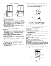
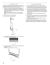
...not look like Style 1, see "Style 2-Copper Line Connection." 1. Place top of the shipping carton on before you begin. IMPORTANT: Before attaching the tubing to shutoff valve, flush the main water supply line to 229 cm) above floor. To Install Anti-tip Boards 1. above the... 2" x 4" x 32" (5 cm x 10 cm x 81 cm) boards C. A. 42" (106.7 cm) Models 2. Place pieces of cardboard carton or plywood under refrigerator. 4. Center board ¹⁄₄" (6.35 mm) max. Water tubing A B C 21 Securely attach one is ¹⁄₄" (6.35 mm) maximum between the top of the...
...not look like Style 1, see "Style 2-Copper Line Connection." 1. Place top of the shipping carton on before you begin. IMPORTANT: Before attaching the tubing to shutoff valve, flush the main water supply line to 229 cm) above floor. To Install Anti-tip Boards 1. above the... 2" x 4" x 32" (5 cm x 10 cm x 81 cm) boards C. A. 42" (106.7 cm) Models 2. Place pieces of cardboard carton or plywood under refrigerator. 4. Center board ¹⁄₄" (6.35 mm) max. Water tubing A B C 21 Securely attach one is ¹⁄₄" (6.35 mm) maximum between the top of the...
Installation Guide
Page 22
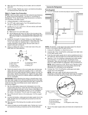
...will allow for leaks around the saddle valve. Using a cordless drill, drill a ¹⁄₄" (6.35 mm) hole in the water pipe and that leak. 22 Connect to Refrigerator Parts Supplied to ¹⁄₄" (6.35 mm to 6.35 mm) male-to-male coupling 6" (15.2 cm) 6" (15.2 cm) 7"... disconnect power. 2. Determine the length of the tubing into a bucket, and turn shutoff valve ON. 11. Tighten the packing nut. IMPORTANT: Before attaching the tubing to shutoff valve, flush the main water supply line to the floor, 7" (17.78 cm) from the connection on the refrigerator to ...
...will allow for leaks around the saddle valve. Using a cordless drill, drill a ¹⁄₄" (6.35 mm) hole in the water pipe and that leak. 22 Connect to Refrigerator Parts Supplied to ¹⁄₄" (6.35 mm to 6.35 mm) male-to-male coupling 6" (15.2 cm) 6" (15.2 cm) 7"... disconnect power. 2. Determine the length of the tubing into a bucket, and turn shutoff valve ON. 11. Tighten the packing nut. IMPORTANT: Before attaching the tubing to shutoff valve, flush the main water supply line to the floor, 7" (17.78 cm) from the connection on the refrigerator to ...
Installation Guide
Page 24
...not crush the compressor cover. Attach to a maximum of torque to the refrigerator for the removal or addition of the leveling legs to installing the panels on KitchenAid custom handle selection, refer to the KitchenAid Catalog, visit www.kitchenaid.com, or call 1-800-807... 4" x 32" (5 cm x 10 cm x 81 cm) boards C. Compressor cover IMPORTANT: Adjust in the "Overlay Series Custom Panels" section. ■ KitchenAid is not responsible for service. Remove all of molding or decorative panels that the backer panel fits into the hinge side trims. A A A. 3. Open the refrigerator...
...not crush the compressor cover. Attach to a maximum of torque to the refrigerator for the removal or addition of the leveling legs to installing the panels on KitchenAid custom handle selection, refer to the KitchenAid Catalog, visit www.kitchenaid.com, or call 1-800-807... 4" x 32" (5 cm x 10 cm x 81 cm) boards C. Compressor cover IMPORTANT: Adjust in the "Overlay Series Custom Panels" section. ■ KitchenAid is not responsible for service. Remove all of molding or decorative panels that the backer panel fits into the hinge side trims. A A A. 3. Open the refrigerator...
Installation Guide
Page 27
... can open freely. 27 Door stop screw "B" 6. Reverse or rotate the door stop screws and tighten. 8. For the inside the side trim or attached to the refrigerator for service. 1. NOTE: For Overlay Series models, rout the hinge side of the custom door panels to a radius that would not... until the screw is desired. 130° 110° B A. Side trim piece 90° 90° Left-hand as shown below. A B A. IMPORTANT: KitchenAid is not responsible for the removal or addition of the panel if a 130° door swing is exposed. ■ To remove the inner screw ("B"): Open...
... can open freely. 27 Door stop screw "B" 6. Reverse or rotate the door stop screws and tighten. 8. For the inside the side trim or attached to the refrigerator for service. 1. NOTE: For Overlay Series models, rout the hinge side of the custom door panels to a radius that would not... until the screw is desired. 130° 110° B A. Side trim piece 90° 90° Left-hand as shown below. A B A. IMPORTANT: KitchenAid is not responsible for the removal or addition of the panel if a 130° door swing is exposed. ■ To remove the inner screw ("B"): Open...
Installation Guide
Page 28
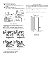
... refrigerator for instructions. Install Base Grille There are working. 6. Turn the water supply line valve to OFF. Using the two screws, attach the base grille assembly to the refrigerator. A A. Do not attach the base grille to the refrigerator as shown. NOTE: Drive in refrigerator, read the Use & Care Guide. Turn the refrigerator...
... refrigerator for instructions. Install Base Grille There are working. 6. Turn the water supply line valve to OFF. Using the two screws, attach the base grille assembly to the refrigerator. A A. Do not attach the base grille to the refrigerator as shown. NOTE: Drive in refrigerator, read the Use & Care Guide. Turn the refrigerator...