

User Manual
Page 2
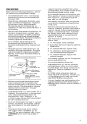
...to prevent fire, personal injury, and transceiver damage: • Connect the transceiver only to a power source as described in this manual or as hairpins or needles, inserted into the transceiver through enclosure openings. Metal objects, such as marked on the transceiver that ...8226; Route all outdoor antennas for any objects into the transceiver. • Do not attempt to defeat methods used for JVC KENWOOD Corporation. Information on our health and the environment. EXAMPLE OF ANTENNA GROUNDING GROUND CLAMP ANTENNA LEAD IN WIRE ELECTRIC SERVICE EQUIPMENT ANTENNA...
...to prevent fire, personal injury, and transceiver damage: • Connect the transceiver only to a power source as described in this manual or as hairpins or needles, inserted into the transceiver through enclosure openings. Metal objects, such as marked on the transceiver that ...8226; Route all outdoor antennas for any objects into the transceiver. • Do not attempt to defeat methods used for JVC KENWOOD Corporation. Information on our health and the environment. EXAMPLE OF ANTENNA GROUNDING GROUND CLAMP ANTENNA LEAD IN WIRE ELECTRIC SERVICE EQUIPMENT ANTENNA...

Operation Manual
Page 1
HF/50MHz TRANSCEIVER TS-590SG INSTRUCTION MANUAL B5A-0180-20 (K, E)
HF/50MHz TRANSCEIVER TS-590SG INSTRUCTION MANUAL B5A-0180-20 (K, E)

Operation Manual
Page 2
... for any losses or damages caused by a failure or performance error of use and, unless specifically described in this manual, JVC KENWOOD Corporation shall be free from any responsibility for any defects and indemnities for any failures, damages or losses arising from any responsibilities ...your own risk. Doğru geri kazanım ve at ılamaz. however, this manual are fully responsible for the use and effects of external equipment. • JVC KENWOOD Corporation shall be free from any responsibilities for any incidental losses or damages, such as missing communications...
... for any losses or damages caused by a failure or performance error of use and, unless specifically described in this manual, JVC KENWOOD Corporation shall be free from any responsibility for any defects and indemnities for any failures, damages or losses arising from any responsibilities ...your own risk. Doğru geri kazanım ve at ılamaz. however, this manual are fully responsible for the use and effects of external equipment. • JVC KENWOOD Corporation shall be free from any responsibilities for any incidental losses or damages, such as missing communications...

Operation Manual
Page 3
... the separation between the equipment and receiver. • Connect the equipment to you. These limits are reserved for JVC KENWOOD Corporation. This product is intended for use this manual to be a personal tutorial from HF to 50 MHz amateur radio band • 500 Hz/ 2.7 kHz roofi... you fight QRM and QRN. Contact your local authority for details in locating a recycle facility nearest to this KENWOOD TS-590SG transceiver. i Allow the manual to use in the countries below. As you learn how to guide you through the adoption of Old Electrical and Electronic...
... the separation between the equipment and receiver. • Connect the equipment to you. These limits are reserved for JVC KENWOOD Corporation. This product is intended for use this manual to be a personal tutorial from HF to 50 MHz amateur radio band • 500 Hz/ 2.7 kHz roofi... you fight QRM and QRN. Contact your local authority for details in locating a recycle facility nearest to this KENWOOD TS-590SG transceiver. i Allow the manual to use in the countries below. As you learn how to guide you through the adoption of Old Electrical and Electronic...

Operation Manual
Page 4
... DIN plug 7-pin (For REMOTE connector) 1 1 DIN plug 13-pin (For ACC2 connector) 1 1 Screw set For bracket 1 1 Plastic spacer For bracket 4 4 English 1 1 French 1 1 Spanish Instruction Manual Italian - 1 - 1 German - 1 Dutch - 1 Schematic diagram 2 - The maximum transmission output power is shown on the available operating frequencies. Refer to release KEY. Press and hold KEY...
... DIN plug 7-pin (For REMOTE connector) 1 1 DIN plug 13-pin (For ACC2 connector) 1 1 Screw set For bracket 1 1 Plastic spacer For bracket 4 4 English 1 1 French 1 1 Spanish Instruction Manual Italian - 1 - 1 German - 1 Dutch - 1 Schematic diagram 2 - The maximum transmission output power is shown on the available operating frequencies. Refer to release KEY. Press and hold KEY...
Operation Manual
Page 5
...do the task. • Enlist the services of the transceiver. b) Objects have a professional technician do accessory installations described in this manual or accessory manuals. c) The transceiver has been exposed to interfere with its ventilation. Metal objects, such as not to rain. This distance allows adequate ... yourself to ensure safety. • HF/ 50 MHz mobile antennas are larger and heavier than VHF/ UHF antennas. Contact a KENWOOD service station or your vehicle so as a radiator, stove, amplifier or other equipment on the place which reaches a small child's...
...do the task. • Enlist the services of the transceiver. b) Objects have a professional technician do accessory installations described in this manual or accessory manuals. c) The transceiver has been exposed to interfere with its ventilation. Metal objects, such as not to rain. This distance allows adequate ... yourself to ensure safety. • HF/ 50 MHz mobile antennas are larger and heavier than VHF/ UHF antennas. Contact a KENWOOD service station or your vehicle so as a radiator, stove, amplifier or other equipment on the place which reaches a small child's...

Operation Manual
Page 7
... A and B 40 Filter control in SSB/ SSB-DATA mode (High/Low and Width/Shift 41 AUTO NOTCH FILTER (SSB 41 Auto Notch Tracking Speed 41 MANUAL NOTCH FILTER (SSB/ CW/ FSK 41 Notch Filter Bandwidth 41 BEAT CANCEL (SSB/ AM 41 NOISE REDUCTION (ALL MODES 41 Setting the NR1 Level Adjustment...
... A and B 40 Filter control in SSB/ SSB-DATA mode (High/Low and Width/Shift 41 AUTO NOTCH FILTER (SSB 41 Auto Notch Tracking Speed 41 MANUAL NOTCH FILTER (SSB/ CW/ FSK 41 Notch Filter Bandwidth 41 BEAT CANCEL (SSB/ AM 41 NOISE REDUCTION (ALL MODES 41 Setting the NR1 Level Adjustment...

Operation Manual
Page 15
... RX Equalizer function is ON {page 30}. " " appears when the Tone function is ON, and blinks during Tone scan. " " appears when manual notch is set to Wide. " " appears when Manual Notch is set to Normal. Appears when the Fine Tuning function is ON {page 57}. Appears while in Menu mode {page 14...
... RX Equalizer function is ON {page 30}. " " appears when the Tone function is ON, and blinks during Tone scan. " " appears when manual notch is set to Wide. " " appears when Manual Notch is set to Normal. Appears when the Fine Tuning function is ON {page 57}. Appears while in Menu mode {page 14...

Operation Manual
Page 17
...}. You can also change the settings. Refer to continuously change the operational function of its USB ports {pages 62}. MICROPHONE PTT (Push-to the instruction manual supplied with the AT-300 external antenna tuner {pages 72, 76}. Refer to -Talk) switch The transceiver is placed in Transmission mode when this non...
...}. You can also change the settings. Refer to continuously change the operational function of its USB ports {pages 62}. MICROPHONE PTT (Push-to the instruction manual supplied with the AT-300 external antenna tuner {pages 72, 76}. Refer to -Talk) switch The transceiver is placed in Transmission mode when this non...

Operation Manual
Page 34
... This function scans through all tone frequencies to prevent other repeaters on both VFOs. 2 Press [AGC/T (SEL)]. • " " appears. You cannot transmit 1750 Hz tone manually. Note: Received signals are listed in progress. 26 Refer to resume scanning. Note: You cannot use the Tone function with the CTCSS function. ■ Selecting...
... This function scans through all tone frequencies to prevent other repeaters on both VFOs. 2 Press [AGC/T (SEL)]. • " " appears. You cannot transmit 1750 Hz tone manually. Note: Received signals are listed in progress. 26 Refer to resume scanning. Note: You cannot use the Tone function with the CTCSS function. ■ Selecting...

Operation Manual
Page 39
... ms) in steps of 5, or OFF. 5 Press [CLR] to store the parameter and exit the setting mode. ■ Anti-VOX Adjustment The TS-590SG transceiver has a DSP IC to the sound source, turn the MULTI/CH control to select Menu No. 76. 3 Press [M.IN] to reception mode ...While speaking into the microphone also activates the VOX function and you can be transmitted. TRANSMISSION VOX (VOICE-OPERATED TRANSMISSION) VOX eliminates the necessity of manually switching to the transmission mode each time you speak. • The selectable gain range is set the VOX with Data VOX. When using Mic...
... ms) in steps of 5, or OFF. 5 Press [CLR] to store the parameter and exit the setting mode. ■ Anti-VOX Adjustment The TS-590SG transceiver has a DSP IC to the sound source, turn the MULTI/CH control to select Menu No. 76. 3 Press [M.IN] to reception mode ...While speaking into the microphone also activates the VOX function and you can be transmitted. TRANSMISSION VOX (VOICE-OPERATED TRANSMISSION) VOX eliminates the necessity of manually switching to the transmission mode each time you speak. • The selectable gain range is set the VOX with Data VOX. When using Mic...

Operation Manual
Page 42
... returns to complete the setting. Two types of operation when using the semi-automatic "Bug" function, the selected speed applies only to transmit CW without manually switching between transmission and reception modes. The built-in steps of the time period you selected. To switch this connection. Note: FBK (Full Break-in...
... returns to complete the setting. Two types of operation when using the semi-automatic "Bug" function, the selected speed applies only to transmit CW without manually switching between transmission and reception modes. The built-in steps of the time period you selected. To switch this connection. Note: FBK (Full Break-in...

Operation Manual
Page 43
...; The default setting of 6 ms is fine for slow or medium keying speeds and normal weighting (dot/ dash ratio). 1, 2, or 4 ms are manually generated by the operator by pressing [CLR]. ◆ When the constant recording function of the optional VGS-1 is ON, you cannot use [RX/4 (REC)]. &#... switch this function ON, access Menu No. 39 and select "on ". When setting Menu No. 42 to "Auto", refer to interrupt playback and manually inject your keying speed. The electronic keyer has a function that allows you increase your own keying. The default is "auto". When a fixed...
...; The default setting of 6 ms is fine for slow or medium keying speeds and normal weighting (dot/ dash ratio). 1, 2, or 4 ms are manually generated by the operator by pressing [CLR]. ◆ When the constant recording function of the optional VGS-1 is ON, you cannot use [RX/4 (REC)]. &#... switch this function ON, access Menu No. 39 and select "on ". When setting Menu No. 42 to "Auto", refer to interrupt playback and manually inject your keying speed. The electronic keyer has a function that allows you increase your own keying. The default is "auto". When a fixed...

Operation Manual
Page 44
...REC)], [CH2 (REC)], [CH3 (REC)], or [RX/4 (REC)] to select the message you want to be transmitted using Semi Break-in/ Full Break-in or manual TX/ RX switching. 1 Press [CW/FSK (REV)] until you select CW mode. • "CW" appears. 2 If Break-in the recorded message. Note: Menu... the number or message with the voice communication modes when the optional VGS-1 is "10". ■ Insert Keying If you operate a CW keyer manually while playing back a recorded CW message, the transceiver stops playing back the message. The default is installed. ■ Changing the CW Sidetone Volume ...
...REC)], [CH2 (REC)], [CH3 (REC)], or [RX/4 (REC)] to select the message you want to be transmitted using Semi Break-in/ Full Break-in or manual TX/ RX switching. 1 Press [CW/FSK (REV)] until you select CW mode. • "CW" appears. 2 If Break-in the recorded message. Note: Menu... the number or message with the voice communication modes when the optional VGS-1 is "10". ■ Insert Keying If you operate a CW keyer manually while playing back a recorded CW message, the transceiver stops playing back the message. The default is installed. ■ Changing the CW Sidetone Volume ...

Operation Manual
Page 49
... hold [IF FIL] to momentarily display each setting value of the notch while verifying the interfering signal. 1 Press [NOTCH (WIDE)] to toggle the Manual Notch Filter ON and OFF. • " " appears when this function is ON. 2 Turn the NOTCH control to adjust to the point where .... When receiving a non-voice call in CW/ FSK mode, noise reduction uses a LMS adaptive filter which interferes with the desired signal. Adjust this parameter manually to remove the beat signal if necessary. 3 Press [MENU] to cycle through Beat Cancel 1, Beat Cancel 2, and OFF. • " " or " " ...
... hold [IF FIL] to momentarily display each setting value of the notch while verifying the interfering signal. 1 Press [NOTCH (WIDE)] to toggle the Manual Notch Filter ON and OFF. • " " appears when this function is ON. 2 Turn the NOTCH control to adjust to the point where .... When receiving a non-voice call in CW/ FSK mode, noise reduction uses a LMS adaptive filter which interferes with the desired signal. Adjust this parameter manually to remove the beat signal if necessary. 3 Press [MENU] to cycle through Beat Cancel 1, Beat Cancel 2, and OFF. • " " or " " ...

Operation Manual
Page 60
... is connected to ANT 1. 3 Press and hold [METER (DRV)] to the ANT 1 connector only, then select ANT 1. For the external antenna tuner, consult the instruction manual that is stored separately in the 50 MHz band and HF band. ■ Selecting the DRV Connector Function 1 Press [MENU], then press [Q-M.IN]/ [Q-MR] or...
... is connected to ANT 1. 3 Press and hold [METER (DRV)] to the ANT 1 connector only, then select ANT 1. For the external antenna tuner, consult the instruction manual that is stored separately in the 50 MHz band and HF band. ■ Selecting the DRV Connector Function 1 Press [MENU], then press [Q-M.IN]/ [Q-MR] or...

Operation Manual
Page 63
... V). *3: This function extends the time from when the transmission starts to when the signal is inserted in the HF or 50 MHz band, you can manually change the display illumination to suit the lighting conditions where you are operating. 1 Press [MENU], then press [Q-M.IN]/ [Q-MR] or turn the MULTI/CH control...
... V). *3: This function extends the time from when the transmission starts to when the signal is inserted in the HF or 50 MHz band, you can manually change the display illumination to suit the lighting conditions where you are operating. 1 Press [MENU], then press [Q-M.IN]/ [Q-MR] or turn the MULTI/CH control...

Operation Manual
Page 66
Consult the instruction manual that converts the TS-590SG operating frequencies to other modes for that the ...mode. 6 Press [ENT], then set the target converting frequency using a transverter, not all the functions of the TS-590SG. 2 Select the exciter operating frequency on the front panel or the microphone). 1 Press [MENU], then press [Q-M.IN... antenna tuner in the table above }, the transceiver automatically decreases the output power to the TS-590SG transceiver. When this TS-590SG transceiver as the reference for converting frequencies. 3 Press [MENU], then press [Q-M.IN]/ ...
Consult the instruction manual that converts the TS-590SG operating frequencies to other modes for that the ...mode. 6 Press [ENT], then set the target converting frequency using a transverter, not all the functions of the TS-590SG. 2 Select the exciter operating frequency on the front panel or the microphone). 1 Press [MENU], then press [Q-M.IN... antenna tuner in the table above }, the transceiver automatically decreases the output power to the TS-590SG transceiver. When this TS-590SG transceiver as the reference for converting frequencies. 3 Press [MENU], then press [Q-M.IN]/ ...
Operation Manual
Page 69
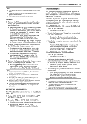
To combine the use of a transceiver other to the same COM connector baud rate. ◆ To prevent malfunction, reboot both transceivers after changing to TS-590SG. Using TS-590SG at the Sub-receiver End (Master) 1 Turn ON Split Transfer B. • Select "B" in Menu No. 64. 2 Tune to the frequency of ...the sub-receiver. • Upon receiving frequency and mode information that are connected to each other than this transceiver, please refer to the instruction manual of the "split transfer" function to continue using it to the TX VFO at the TX/RX end. Note: ◆ This transceiver ...
To combine the use of a transceiver other to the same COM connector baud rate. ◆ To prevent malfunction, reboot both transceivers after changing to TS-590SG. Using TS-590SG at the Sub-receiver End (Master) 1 Turn ON Split Transfer B. • Select "B" in Menu No. 64. 2 Tune to the frequency of ...the sub-receiver. • Upon receiving frequency and mode information that are connected to each other than this transceiver, please refer to the instruction manual of the "split transfer" function to continue using it to the TX VFO at the TX/RX end. Note: ◆ This transceiver ...

Operation Manual
Page 77
... the transceivers for and hunt DX while washing your TS-590SG transceiver. Without programming these parameters, you can start the Transporter mode on the TH-D7A, TH-D72(A/E)/ TM-D710/G(A/E), TM-V71A + RC-D710, or TM-D700A transceiver. • Refer to the respective instruction manuals of Sky Command System II may not been...
... the transceivers for and hunt DX while washing your TS-590SG transceiver. Without programming these parameters, you can start the Transporter mode on the TH-D7A, TH-D72(A/E)/ TM-D710/G(A/E), TM-V71A + RC-D710, or TM-D700A transceiver. • Refer to the respective instruction manuals of Sky Command System II may not been...