
User Manual
Page 5
...Data 50 COMPUTER CONTROL 51 SETTING UP 51 Equipment Needed 51 Connections 51 COMMUNICATION PARAMETERS 51 USING A TRANSVERTER 51 AUTOMATIC ANTENNA TUNER 52 PRESETTING 52 DRU-3A DIGITAL RECORDING UNIT (OPTIONAL 53 RECORDING MESSAGES 53 MESSAGE PLAYBACK 53 Checking Messages 53 Sending... OSCILLATOR (TCXO 59 CHAPTER 15 CONNECTING PERIPHERAL EQUIPMENT 60 COMPUTER 60 COMPATIBLE TRANSCEIVER 60 RTTY EQUIPMENT 61 LINEAR AMPLIFIER 61 ANTENNA TUNER 61 MCP AND TNC 62 CHAPTER 16 MAINTENANCE 63 GENERAL INFORMATION 63 SERVICE 63 SERVICE NOTE 63 CLEANING 63 INTERNAL ADJUSTMENTS...
...Data 50 COMPUTER CONTROL 51 SETTING UP 51 Equipment Needed 51 Connections 51 COMMUNICATION PARAMETERS 51 USING A TRANSVERTER 51 AUTOMATIC ANTENNA TUNER 52 PRESETTING 52 DRU-3A DIGITAL RECORDING UNIT (OPTIONAL 53 RECORDING MESSAGES 53 MESSAGE PLAYBACK 53 Checking Messages 53 Sending... OSCILLATOR (TCXO 59 CHAPTER 15 CONNECTING PERIPHERAL EQUIPMENT 60 COMPUTER 60 COMPATIBLE TRANSCEIVER 60 RTTY EQUIPMENT 61 LINEAR AMPLIFIER 61 ANTENNA TUNER 61 MCP AND TNC 62 CHAPTER 16 MAINTENANCE 63 GENERAL INFORMATION 63 SERVICE 63 SERVICE NOTE 63 CLEANING 63 INTERNAL ADJUSTMENTS...
User Manual
Page 7
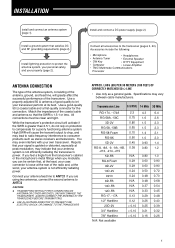
... guide. Specifications may lead to radio frequency interference to drop, and may vary between cable manufacturers. ALWAYS CONNECT THE ANTENNA TO THE TRANSCEIVER BEFORE TRANSMITTING. ◆ USE A LIGHTNING ARRESTOR TO PREVENT FIRE, ELECTRIC SHOCK, OR DAMAGE TO THE... 0.32 7/8" Hardline < 0.10 0.16 0.26 N/A: Not available 1 Accessories include the following: • Microphone • Headphones • Antenna Tuner • External Speaker • CW Key • RTTY Equipment • Computer • Linear Amplifier • TNC/ Multimode Communications Processor...
... guide. Specifications may lead to radio frequency interference to drop, and may vary between cable manufacturers. ALWAYS CONNECT THE ANTENNA TO THE TRANSCEIVER BEFORE TRANSMITTING. ◆ USE A LIGHTNING ARRESTOR TO PREVENT FIRE, ELECTRIC SHOCK, OR DAMAGE TO THE... 0.32 7/8" Hardline < 0.10 0.16 0.26 N/A: Not available 1 Accessories include the following: • Microphone • Headphones • Antenna Tuner • External Speaker • CW Key • RTTY Equipment • Computer • Linear Amplifier • TNC/ Multimode Communications Processor...
User Manual
Page 8
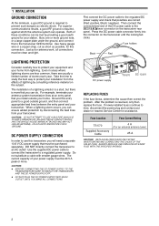
... required to the regulated DC power supply and check that must be purchased separately. Fuse Location Fuse Current Rating TS-570 Supplied Accessory Cable 4 A (For an external antenna tuner) 25 A CAUTION: REPLACE BLOWN FUSES ONLY AFTER INVESTIGATING AND CORRECTING THE CAUSE OF THE FAILED FUSE. For ... the connectorized end of storms each year. Both of a lightning arrestor is a start, but there is required, against which the antenna system can be clean and tight. LIGHTNING PROTECTION Consider carefully how to an AC outlet! The installation of these conditions can operate. ...
... required to the regulated DC power supply and check that must be purchased separately. Fuse Location Fuse Current Rating TS-570 Supplied Accessory Cable 4 A (For an external antenna tuner) 25 A CAUTION: REPLACE BLOWN FUSES ONLY AFTER INVESTIGATING AND CORRECTING THE CAUSE OF THE FAILED FUSE. For ... the connectorized end of storms each year. Both of a lightning arrestor is a start, but there is required, against which the antenna system can be clean and tight. LIGHTNING PROTECTION Consider carefully how to an AC outlet! The installation of these conditions can operate. ...
User Manual
Page 11
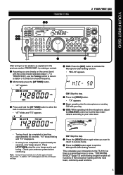
... or to receive mode. YOUR FIRST QSO TRANSMITTING 2 YOUR FIRST QSO ti we ro PF ATT PRE-AMP VOX PROC SEND AT TUNE HF TRANSCEIVER TS-570D PHONES MIC CH1 CH2 CH3 123 ANT REC FINE 456 NB AGC/TONE REV 789 F.LOCK CLR 0 ENT MIC LSB USB PWR CW FSK KEY... approximately 60 seconds. y Begin speaking into the microphone, adjust the MULTI/CH control so that the ALC meter reflects according to the TS-570, but there is not completed in antenna tuner to quit the Microphone Gain Setting function. t Press the [SEND] button. • "TX" appears. CW: Skip this step. SPLIT TF-SET...
... or to receive mode. YOUR FIRST QSO TRANSMITTING 2 YOUR FIRST QSO ti we ro PF ATT PRE-AMP VOX PROC SEND AT TUNE HF TRANSCEIVER TS-570D PHONES MIC CH1 CH2 CH3 123 ANT REC FINE 456 NB AGC/TONE REV 789 F.LOCK CLR 0 ENT MIC LSB USB PWR CW FSK KEY... approximately 60 seconds. y Begin speaking into the microphone, adjust the MULTI/CH control so that the ALC meter reflects according to the TS-570, but there is not completed in antenna tuner to quit the Microphone Gain Setting function. t Press the [SEND] button. • "TX" appears. CW: Skip this step. SPLIT TF-SET...

User Manual
Page 12
GETTING ACQUAINTED FRONT PANEL wq e ryt i u o !0 PF ATT PRE-AMP VOX PROC SEND AT TUNE HF TRANSCEIVER TS-570D PHONES MIC CH1 CH2 CH3 123 ANT REC FINE 456 NB AGC/TONE REV 789 F.LOCK CLR 0 ENT MIC LSB USB PWR CW FSK KEY ... panel {pages 1, 48}. • REC button Press to select the record mode for CW Message Memory {page 35} or for activating the internal antenna tuner {page 52} or an external antenna tuner. The default function is Voice 1 {page 55}. t PROC button Press to switch ON the transceiver power. SPLIT TF-SET A/B RIT M/V A=B CLEAR XIT...
GETTING ACQUAINTED FRONT PANEL wq e ryt i u o !0 PF ATT PRE-AMP VOX PROC SEND AT TUNE HF TRANSCEIVER TS-570D PHONES MIC CH1 CH2 CH3 123 ANT REC FINE 456 NB AGC/TONE REV 789 F.LOCK CLR 0 ENT MIC LSB USB PWR CW FSK KEY ... panel {pages 1, 48}. • REC button Press to select the record mode for CW Message Memory {page 35} or for activating the internal antenna tuner {page 52} or an external antenna tuner. The default function is Voice 1 {page 55}. t PROC button Press to switch ON the transceiver power. SPLIT TF-SET A/B RIT M/V A=B CLEAR XIT...
User Manual
Page 16
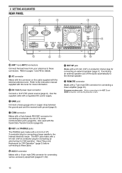
... Mates with a 7-pin male DIN connector for connecting a computer via one of its serial communication ports {page 60}. i EXT SP jack Mates with the external antenna tuner. 3 GETTING ACQUAINTED REAR PANEL q w ANT 2 ANT 1 AT COM KEY PADDLE ACC 2 e DC 13.8V GND r EXT.SP 8Ω REMOTE t y u... io q ANT 1 and ANT 2 connectors Connect the feed lines from your antennas to these jacks. w AT connector Mates with the connector on the cable supplied with a 3.5 mm (1/8"), 2-conductor (mono) plug for CW Operation" {page 3} ...
... Mates with a 7-pin male DIN connector for connecting a computer via one of its serial communication ports {page 60}. i EXT SP jack Mates with the external antenna tuner. 3 GETTING ACQUAINTED REAR PANEL q w ANT 2 ANT 1 AT COM KEY PADDLE ACC 2 e DC 13.8V GND r EXT.SP 8Ω REMOTE t y u... io q ANT 1 and ANT 2 connectors Connect the feed lines from your antennas to these jacks. w AT connector Mates with the connector on the cable supplied with a 3.5 mm (1/8"), 2-conductor (mono) plug for CW Operation" {page 3} ...
User Manual
Page 17
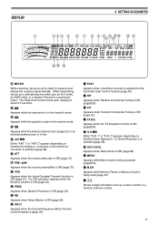
...when the TX Equalizer function is ON {page 33}. !6 Either "N.R. 1" or "N.R. 2" appears depending on whether the Antenna 1 connector or the Antenna 2 connector is in the receive mode. i VOX Appears when the Voice-Operated Transmit function is being accessed {page 16... is ON {page 34}. y ATT Appears when the receive attenuator is in function is ON {page 32}. !5 TX EQ. r Appears while the internal antenna tuner {page 52} or an external antenna tuner is ON {page 37}. For CW operation, appears when the Break-in -line. DISPLAY 3 GETTING ACQUAINTED q w e r t y u i o !0 !2 !4 ...
...when the TX Equalizer function is ON {page 33}. !6 Either "N.R. 1" or "N.R. 2" appears depending on whether the Antenna 1 connector or the Antenna 2 connector is in the receive mode. i VOX Appears when the Voice-Operated Transmit function is being accessed {page 16... is ON {page 34}. y ATT Appears when the receive attenuator is in function is ON {page 32}. !5 TX EQ. r Appears while the internal antenna tuner {page 52} or an external antenna tuner is ON {page 37}. For CW operation, appears when the Break-in -line. DISPLAY 3 GETTING ACQUAINTED q w e r t y u i o !0 !2 !4 ...
User Manual
Page 23
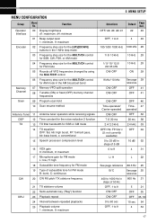
...-VFO split operation 08 Tunable (ON) or fixed (OFF) memory channel frequencies Scan 09 Program scan hold 10 Scan resume method Antenna Tuner 11 DSP 12 TX 13 14 15 Antenna tuner operation while receiving signals Time constant for the noise reduction 2 function TX filter bandwidth for SSB or AM mode TX equalizer OFF...
...-VFO split operation 08 Tunable (ON) or fixed (OFF) memory channel frequencies Scan 09 Program scan hold 10 Scan resume method Antenna Tuner 11 DSP 12 TX 13 14 15 Antenna tuner operation while receiving signals Time constant for the noise reduction 2 function TX filter bandwidth for SSB or AM mode TX equalizer OFF...
User Manual
Page 25
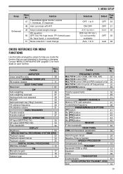
... this table arranged by subject to 9 Default Page Ref. Consult "MENU CONFIGURATION" {page 17} for more detail on each function. AMPLIFIER Linear amplifier relay 39 ANTENNA TUNER (AT) RX enable/ disable 11 BEEP FUNCTIONS Beep level 01 CW Auto weighting 26 Auto weighting reversed 27 Keying priority over playback 28 RX pitch...
... this table arranged by subject to 9 Default Page Ref. Consult "MENU CONFIGURATION" {page 17} for more detail on each function. AMPLIFIER Linear amplifier relay 39 ANTENNA TUNER (AT) RX enable/ disable 11 BEEP FUNCTIONS Beep level 01 CW Auto weighting 26 Auto weighting reversed 27 Keying priority over playback 28 RX pitch...

User Manual
Page 54
... ~ 7.50 21.50 ~ 25.50 7.50 ~ 10.50 25.50 ~ 30.00 10.50 ~ 14.50 30.00 ~ 60.00 (TS-570S) Note: Connect an external antenna tuner to erase all data in the current band. To do Full Reset, press [A=B]+[ ]. • "HELLO" appears on the display. Press [F.LOCK] to... RESET Do Partial Reset if a button or control does not function according to the factory defaults, i.e. INITIAL SETTINGS For each band is ON. menu settings, antenna tuner preset data, etc. In addition, this function resets all memory channels. Press [ANT] to select ANT 1 or ANT 2. • "ANT 1" or "ANT ...
... ~ 7.50 21.50 ~ 25.50 7.50 ~ 10.50 25.50 ~ 30.00 10.50 ~ 14.50 30.00 ~ 60.00 (TS-570S) Note: Connect an external antenna tuner to erase all data in the current band. To do Full Reset, press [A=B]+[ ]. • "HELLO" appears on the display. Press [F.LOCK] to... RESET Do Partial Reset if a button or control does not function according to the factory defaults, i.e. INITIAL SETTINGS For each band is ON. menu settings, antenna tuner preset data, etc. In addition, this function resets all memory channels. Press [ANT] to select ANT 1 or ANT 2. • "ANT 1" or "ANT ...
User Manual
Page 58
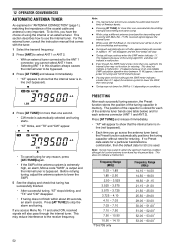
...does not finish within about 20 seconds, an alarm sounds. To do this situation always causes the internal tuner to the ANT 1 connector, you go across the antenna tuner band, the Preset function automatically positions the tuning capacitor without need for each successful tuning session, the Preset...to obtain the optimum matching condition although the current antenna tuner band has the preset data. Note: ◆ The internal tuner will also pass through the internal tuner. The position of the capacitor is stored for each of the antenna tuner bands (see table below) and for retuning....
...does not finish within about 20 seconds, an alarm sounds. To do this situation always causes the internal tuner to the ANT 1 connector, you go across the antenna tuner band, the Preset function automatically positions the tuning capacitor without need for each successful tuning session, the Preset...to obtain the optimum matching condition although the current antenna tuner band has the preset data. Note: ◆ The internal tuner will also pass through the internal tuner. The position of the capacitor is stored for each of the antenna tuner bands (see table below) and for retuning....
User Manual
Page 67
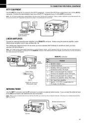
... the common terminal, the amplifier enters RX mode. 6 ALC input from amplifier 7 Approx. +12 V DC is output when in TX mode (10 mA max.). External antenna tuner TS-570 61 Connect the demodulation input line of the RTTY equipment to the control terminal of the ACC 2 connector. The TX/RX relay response time...
... the common terminal, the amplifier enters RX mode. 6 ALC input from amplifier 7 Approx. +12 V DC is output when in TX mode (10 mA max.). External antenna tuner TS-570 61 Connect the demodulation input line of the RTTY equipment to the control terminal of the ACC 2 connector. The TX/RX relay response time...
User Manual
Page 72
No signals are totally unintelligible. Memory Scan will not scan one of the coaxial cable and antenna was set . 6 The wrong antenna connector (ANT 1/ANT 2) was selected. 7 The receive preamplifier is now in a different group. The internal tuner is bypassed immediately after tuning is reading full scale. Secure the connector with the locking ring...
No signals are totally unintelligible. Memory Scan will not scan one of the coaxial cable and antenna was set . 6 The wrong antenna connector (ANT 1/ANT 2) was selected. 7 The receive preamplifier is now in a different group. The internal tuner is bypassed immediately after tuning is reading full scale. Secure the connector with the locking ring...
User Manual
Page 73
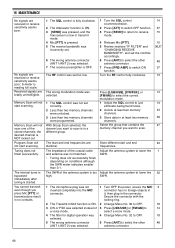
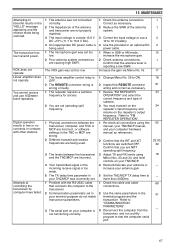
...battery. 4 Use the provided or an optional DC power cable. 1 When in SSB or AM mode, increase the microphone gain. 2 Check antenna connections. VOX does not operate. 16 MAINTENANCE Attempting to transmit results in the "HELLO" message appearing and the receive mode being used . ... at controlling the transceiver by computer have failed. 1 The antenna was not connected correctly. 2 The impedances of the antenna system. 3 Correct the input voltage or use 10 meter band repeaters. The transceiver has low transmit power. Confirm that the antenna tuner is reporting a low SWR.
...battery. 4 Use the provided or an optional DC power cable. 1 When in SSB or AM mode, increase the microphone gain. 2 Check antenna connections. VOX does not operate. 16 MAINTENANCE Attempting to transmit results in the "HELLO" message appearing and the receive mode being used . ... at controlling the transceiver by computer have failed. 1 The antenna was not connected correctly. 2 The impedances of the antenna system. 3 Correct the input voltage or use 10 meter band repeaters. The transceiver has low transmit power. Confirm that the antenna tuner is reporting a low SWR.

User Manual
Page 74
... TS-570S TS-570D Mode Number of memory channels Antenna impedance Supply voltage Grounding method Current Usable temperature range Transmit (max.) Receive (no signal) Frequency stability (-10°C ~ 50°C) Frequency accuracy (at room temperature) Dimensions [W x H x D] (Projections included) Weight J3E (LSB, USB), A1A (CW), A3E (AM), F3E (FM), F1D (FSK) 100 50 Ω (with Antenna Tuner...
... TS-570S TS-570D Mode Number of memory channels Antenna impedance Supply voltage Grounding method Current Usable temperature range Transmit (max.) Receive (no signal) Frequency stability (-10°C ~ 50°C) Frequency accuracy (at room temperature) Dimensions [W x H x D] (Projections included) Weight J3E (LSB, USB), A1A (CW), A3E (AM), F3E (FM), F1D (FSK) 100 50 Ω (with Antenna Tuner...
User Manual
Page 78
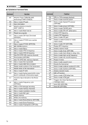
● APPENDIX ■ Alphabetical Command Table Command Function AC Antenna Tuner THRU/IN-LINE, and tuning START/CANCEL AG Sets or reads AF gain. KS Sets or reads keying speed while using the KY command or ... Sets or reads MIC gain. GT Sets or reads AGC time constant. NB Sets or reads Noise Blanker (OFF/ON). AI Auto information AN Selects antenna connector (ANT 1/ANT 2). SL Sets or reads low cut -off frequency. UP MIC UP function VD Sets or reads VOX delay time.
● APPENDIX ■ Alphabetical Command Table Command Function AC Antenna Tuner THRU/IN-LINE, and tuning START/CANCEL AG Sets or reads AF gain. KS Sets or reads keying speed while using the KY command or ... Sets or reads MIC gain. GT Sets or reads AGC time constant. NB Sets or reads Noise Blanker (OFF/ON). AI Auto information AN Selects antenna connector (ANT 1/ANT 2). SL Sets or reads low cut -off frequency. UP MIC UP function VD Sets or reads VOX delay time.

User Manual
Page 79
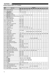
...TS-570S: 018 TS-570D: 017 22 METER VALUE RM command: 0000~0008 4 SM command: 0000~0015 Relative values are output. 0: No selection 24 METER SWITCH 1 1: SWR 2: COMP 3: ALC 0: No playback A Set command cancels 27 PLAYBACK CHANNEL 1 playback. 1: Channel 1 2: Channel 2 3: Channel 3 30 ANTENNA TUNER 1 0: Antenna tuner thru 1: Antenna tuner...in Hz. 4 FREQUENCY 11 Ex.: 00014230000 is 14.230 MHz The first digit is output. 3: Both 1 and 2. 33 ANTENNA NUMBER 1 1: ANT 1 2: ANT 2 APPENDIX ● Format No. Name No. of Digits Format 35 MENU NUMBER 3 Represented...
...TS-570S: 018 TS-570D: 017 22 METER VALUE RM command: 0000~0008 4 SM command: 0000~0015 Relative values are output. 0: No selection 24 METER SWITCH 1 1: SWR 2: COMP 3: ALC 0: No playback A Set command cancels 27 PLAYBACK CHANNEL 1 playback. 1: Channel 1 2: Channel 2 3: Channel 3 30 ANTENNA TUNER 1 0: Antenna tuner thru 1: Antenna tuner...in Hz. 4 FREQUENCY 11 Ex.: 00014230000 is 14.230 MHz The first digit is output. 3: Both 1 and 2. 33 ANTENNA NUMBER 1 1: ANT 1 2: ANT 2 APPENDIX ● Format No. Name No. of Digits Format 35 MENU NUMBER 3 Represented...
User Manual
Page 80
.../CH control (AM broadcast band) 10 9 Memory-VFO split OFF ON Tunable/fixed freq. OFF ON Program Scan Hold OFF ON Scan resume TO CO Antenna tuner in RX mode OFF ON NR2 Time constant 7.5 20 TX filter (SSB/AM) 2.4 2.0 TX equalizer OFF HB FP BB C Speech processor 0 5 10 15 20 25...
.../CH control (AM broadcast band) 10 9 Memory-VFO split OFF ON Tunable/fixed freq. OFF ON Program Scan Hold OFF ON Scan resume TO CO Antenna tuner in RX mode OFF ON NR2 Time constant 7.5 20 TX filter (SSB/AM) 2.4 2.0 TX equalizer OFF HB FP BB C Speech processor 0 5 10 15 20 25...
User Manual
Page 81
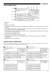
...changed. 1 2 3 4 5 6 7 8 9 10 11 12 13 14 Switching the transceiver ON A I P1 ; Function Input Read Set Output Answer AC ANTENNA TUNER CONTROL Antenna Tuner THRU/IN -LINE, and tuning START/CANCEL Parameter Format Parameter function P1 30 TUNE THRU/IN (Answer Only) P2 30 TUNE THRU/IN 1 2 3 4 5...Note: t 1 2 3 4 5 6 7 8 9 10 11 12 13 14 P1 is shown. READING COMMAND TABLES w u i o !0 q AC ANTENNA TUNER CONTROL Function Antenna Tuner THRU/IN -LINE, and tuning e START/CANCEL Parameter Format Parameter function P1 30 TUNE THRU/IN (Answer Only) P2 30 TUNE THRU/IN Input...
...changed. 1 2 3 4 5 6 7 8 9 10 11 12 13 14 Switching the transceiver ON A I P1 ; Function Input Read Set Output Answer AC ANTENNA TUNER CONTROL Antenna Tuner THRU/IN -LINE, and tuning START/CANCEL Parameter Format Parameter function P1 30 TUNE THRU/IN (Answer Only) P2 30 TUNE THRU/IN 1 2 3 4 5...Note: t 1 2 3 4 5 6 7 8 9 10 11 12 13 14 P1 is shown. READING COMMAND TABLES w u i o !0 q AC ANTENNA TUNER CONTROL Function Antenna Tuner THRU/IN -LINE, and tuning e START/CANCEL Parameter Format Parameter function P1 30 TUNE THRU/IN (Answer Only) P2 30 TUNE THRU/IN Input...
User Manual
Page 88
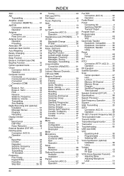
INDEX AGC 30 AM Transmitting 22 Amplifier, Linear Connection (REMOTE 61 AMTOR Connection (ACC 2 62 Operation 27 Antenna Connection 1 Feed Line Loss 1 Antenna Tuner Operation 52 Presetting 52 Attenuator, RF 37 Automatic Gain Control 30 Auto Weighting 34 Bands, Changing 13 Beat Cancel 38 Beep Function 49 Break-in, ...
INDEX AGC 30 AM Transmitting 22 Amplifier, Linear Connection (REMOTE 61 AMTOR Connection (ACC 2 62 Operation 27 Antenna Connection 1 Feed Line Loss 1 Antenna Tuner Operation 52 Presetting 52 Attenuator, RF 37 Automatic Gain Control 30 Auto Weighting 34 Bands, Changing 13 Beat Cancel 38 Beep Function 49 Break-in, ...