
User Manual
Page 2
KENWOOD believes that 's simple to purchase this manual. 6 TH-G71A: 144/440 MHz FM Dual Bander (U.S.A./ Canada) 7 TH-G71A: 144/430 MHz FM Dual Bander 8 (General market) TH-G71E: 144/430 MHz FM Dual Bander 9 (Europe) This transceiver has the following main features. • Contains a total of ... Tone Coded Squelch System (CTCSS) rejects unwanted calls from other persons who are using the same frequency. • Equipped with a high performance antenna. • Illuminates the keys on the keypad as well as a callsign or repeater name. • If programmed, the built-in the dark...
KENWOOD believes that 's simple to purchase this manual. 6 TH-G71A: 144/440 MHz FM Dual Bander (U.S.A./ Canada) 7 TH-G71A: 144/430 MHz FM Dual Bander 8 (General market) TH-G71E: 144/430 MHz FM Dual Bander 9 (Europe) This transceiver has the following main features. • Contains a total of ... Tone Coded Squelch System (CTCSS) rejects unwanted calls from other persons who are using the same frequency. • Equipped with a high performance antenna. • Illuminates the keys on the keypad as well as a callsign or repeater name. • If programmed, the built-in the dark...
User Manual
Page 3
... equipment and receiver. • Connect the equipment to provide reasonable protection against harmful interference in the instruction manual. Contact a 13 KENWOOD service station or your area, call (toll free) 1-800-8-BATTERY (1-800-822-8837). One or more of the following statements may... does cause harmful interference to radio or television reception, which is part of the following measures: • Reorient or relocate the receiving antenna. • Increase the separation between 6 V and 16 V to prevent damaging the transceiver. 6 • When connecting the transceiver ...
... equipment and receiver. • Connect the equipment to provide reasonable protection against harmful interference in the instruction manual. Contact a 13 KENWOOD service station or your area, call (toll free) 1-800-8-BATTERY (1-800-822-8837). One or more of the following statements may... does cause harmful interference to radio or television reception, which is part of the following measures: • Reorient or relocate the receiving antenna. • Increase the separation between 6 V and 16 V to prevent damaging the transceiver. 6 • When connecting the transceiver ...
User Manual
Page 4
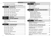
... q PREPARATION CHAPTER t MENU SET-UP WHAT IS A MENU 10 MENU ACCESS 10 3 BATTERY OPERATING TIME 2 INSTALLING THE NiCd BATTERY PACK 2 4 INSTALLING ALKALINE BATTERIES 3 5 INSTALLING THE ANTENNA 4 ATTACHING THE HAND STRAP 4 6 INSTALLING THE BELT HOOK 4 7 CHAPTER w FIRST QSO CHAPTER e GETTING ACQUAINTED 8 ORIENTATION 6 9 BASIC TRANSCEIVER MODES 6 DISPLAY 7 10 CHAPTER r OPERATING BASICS 11 SWITCHING...
... q PREPARATION CHAPTER t MENU SET-UP WHAT IS A MENU 10 MENU ACCESS 10 3 BATTERY OPERATING TIME 2 INSTALLING THE NiCd BATTERY PACK 2 4 INSTALLING ALKALINE BATTERIES 3 5 INSTALLING THE ANTENNA 4 ATTACHING THE HAND STRAP 4 6 INSTALLING THE BELT HOOK 4 7 CHAPTER w FIRST QSO CHAPTER e GETTING ACQUAINTED 8 ORIENTATION 6 9 BASIC TRANSCEIVER MODES 6 DISPLAY 7 10 CHAPTER r OPERATING BASICS 11 SWITCHING...
User Manual
Page 7
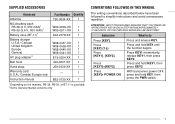
..., then press KEY2. 7 Press and hold KEY1, then press KEY2. 8 With transceiver power OFF, 9 press and hold KEY until 5 the function begins. SUPPLIED ACCESSORIES Accessory Antenna Part Number Quantity T90-0634-XX 1 NiCd battery pack PB-38 (6 V, 650 mAh)1 PB-39 (9.6 V, 600 mAh)1 Battery case (BT-11)1 W09-0909-XX 1 W09...
..., then press KEY2. 7 Press and hold KEY1, then press KEY2. 8 With transceiver power OFF, 9 press and hold KEY until 5 the function begins. SUPPLIED ACCESSORIES Accessory Antenna Part Number Quantity T90-0634-XX 1 NiCd battery pack PB-38 (6 V, 650 mAh)1 PB-39 (9.6 V, 600 mAh)1 Battery case (BT-11)1 W09-0909-XX 1 W09...

User Manual
Page 10
To remove the belt hook, pull the belt hook downward while pushing its base, and screw the antenna into the connector on the top panel of the transceiver until it is snug. 2 3 q w 4 5 6 7 8 9 ATTACHING THE HAND STRAP 10 If you want, attach the provided ... position the cable over the right groove. Last position the cable over the left groove on the transceiver. Then install the belt hook. INSTALLING THE ANTENNA 1 Hold the provided antenna at its tabs from both sides.
To remove the belt hook, pull the belt hook downward while pushing its base, and screw the antenna into the connector on the top panel of the transceiver until it is snug. 2 3 q w 4 5 6 7 8 9 ATTACHING THE HAND STRAP 10 If you want, attach the provided ... position the cable over the right groove. Last position the cable over the left groove on the transceiver. Then install the belt hook. INSTALLING THE ANTENNA 1 Hold the provided antenna at its tabs from both sides.

User Manual
Page 11
... OPERATION IN THE HIGH POWER MODE 3 MAY CAUSE THE BACK OF THE TRANSCEIVER TO GET HOT. ◆ TRANSMITTING WITH THE SUPPLIED 4 ANTENNA NEAR OTHER ELECTRONIC EQUIPMENT CAN INTERFERE WITH THAT EQUIPMENT. FIRST QSO The 7 steps given here will , however, also hear background noise. ...enjoy the exhilaration that comes with opening a brand new transceiver. ALSO, TRANSMITTING NEAR 5 r A REGULATED POWER SUPPLY, THAT IS w NOT RECOMMENDED BY KENWOOD, MAY 6 CAUSE THE POWER SUPPLY TO OUTPUT AN EXTREMELY HIGH VOLTAGE. e Press [BAND] to continue communication. e y Release the PTT switch to ...
... OPERATION IN THE HIGH POWER MODE 3 MAY CAUSE THE BACK OF THE TRANSCEIVER TO GET HOT. ◆ TRANSMITTING WITH THE SUPPLIED 4 ANTENNA NEAR OTHER ELECTRONIC EQUIPMENT CAN INTERFERE WITH THAT EQUIPMENT. FIRST QSO The 7 steps given here will , however, also hear background noise. ...enjoy the exhilaration that comes with opening a brand new transceiver. ALSO, TRANSMITTING NEAR 5 r A REGULATED POWER SUPPLY, THAT IS w NOT RECOMMENDED BY KENWOOD, MAY 6 CAUSE THE POWER SUPPLY TO OUTPUT AN EXTREMELY HIGH VOLTAGE. e Press [BAND] to continue communication. e y Release the PTT switch to ...

User Manual
Page 12
... Tuning control. In this mode you can select on this mode unless you program one memory channel at least. For further information, refer to select. Antenna Tuning control VOL control On Air/Busy lamp Display Speaker/ Microphone SP jack MIC jack Keypad DC IN jack Memory Recall mode Press [MR] to...
... Tuning control. In this mode you can select on this mode unless you program one memory channel at least. For further information, refer to select. Antenna Tuning control VOL control On Air/Busy lamp Display Speaker/ Microphone SP jack MIC jack Keypad DC IN jack Memory Recall mode Press [MR] to...
User Manual
Page 51
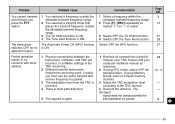
... offset that 2 Press [F], [REV] repeatedly so 13 2 switch. incorrect, or software settings in no is multi-path distortion. according to the TNC manual. 4 Reorient the antenna. You cannot transmit 1 You selected a frequency outside neither "+" nor "-" is open. the allowable transmit frequency 3 range. 3 The TX Inhibit function is ON. 3 Switch OFF the...
... offset that 2 Press [F], [REV] repeatedly so 13 2 switch. incorrect, or software settings in no is multi-path distortion. according to the TNC manual. 4 Reorient the antenna. You cannot transmit 1 You selected a frequency outside neither "+" nor "-" is open. the allowable transmit frequency 3 range. 3 The TX Inhibit function is ON. 3 Switch OFF the...

User Manual
Page 55
..., 6.0 V (battery terminals) Transmit with LO, 6.0 V (battery terminals) Transmit with EL, 6.0 V (battery terminals) Ground method Dimensions (W x H x D, projections not included) 1 Weight 1, 2 Microphone impedance Antenna impedance 1 With a PB-38 installed 2 PB-38, antenna, and belt hook included VHF Band UHF Band 2 144 to 148 MHz 438 to 450 MHz 144 to 148 MHz 430 to...
..., 6.0 V (battery terminals) Transmit with LO, 6.0 V (battery terminals) Transmit with EL, 6.0 V (battery terminals) Ground method Dimensions (W x H x D, projections not included) 1 Weight 1, 2 Microphone impedance Antenna impedance 1 With a PB-38 installed 2 PB-38, antenna, and belt hook included VHF Band UHF Band 2 144 to 148 MHz 438 to 450 MHz 144 to 148 MHz 430 to...

User Manual
Page 59
... Numbers .......... 35 Making Calls 34 Storing Numbers 35 Tone TX Hold 34 Transmitting Stored Numbers ........ 36 Frequency, Selecting 9, 40 Frequency Step Size 40 INDEX Installation Antenna 4 Belt hook 4 Hand strap 4 Keypad Direct Entry Frequency 40 Memory Channel Number 40 Lamp Function 38 Lock, Transceiver 37 Maintenance 42 Memory Channels Clearing 19...
... Numbers .......... 35 Making Calls 34 Storing Numbers 35 Tone TX Hold 34 Transmitting Stored Numbers ........ 36 Frequency, Selecting 9, 40 Frequency Step Size 40 INDEX Installation Antenna 4 Belt hook 4 Hand strap 4 Keypad Direct Entry Frequency 40 Memory Channel Number 40 Lamp Function 38 Lock, Transceiver 37 Maintenance 42 Memory Channels Clearing 19...