
User Manual
Page 1
Model KR-897 is not available in except for two models. Model availability and features (functions) may differ depending on country and sales area. and Canada. B60-3069-00 CS (K, P, Y) MC 98/12 11 10 9 8 7 6 5 4 3 2 1 97/12 11 10 9 8 7 6 5 4 3 2 1 AUDIO VIDEO SURROUND RECEIVER KR-897 KR-797 INSTRUCTION MANUAL KENWOOD CORPORATION This manual contains instructions for U.S.A.
Model KR-897 is not available in except for two models. Model availability and features (functions) may differ depending on country and sales area. and Canada. B60-3069-00 CS (K, P, Y) MC 98/12 11 10 9 8 7 6 5 4 3 2 1 97/12 11 10 9 8 7 6 5 4 3 2 1 AUDIO VIDEO SURROUND RECEIVER KR-897 KR-797 INSTRUCTION MANUAL KENWOOD CORPORATION This manual contains instructions for U.S.A.
User Manual
Page 4
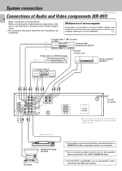
When connecting the related system components, refer Malfunction of microcomputer also to the instruction manuals of the related components. 3 Do not plug in other areas than that indicated on the socket at the rear of the unit. computer referring ...should be connected when a KENWOOD audio component system is connected. *2 Do not connect system control cord to the cassette deck connected to "In case of Audio and Video components (KR-897) 4 Make connection as shown below. If operation is larger than the USA and Canada. System connection KR-897/KR-797 (En) Connections of ...
When connecting the related system components, refer Malfunction of microcomputer also to the instruction manuals of the related components. 3 Do not plug in other areas than that indicated on the socket at the rear of the unit. computer referring ...should be connected when a KENWOOD audio component system is connected. *2 Do not connect system control cord to the cassette deck connected to "In case of Audio and Video components (KR-897) 4 Make connection as shown below. If operation is larger than the USA and Canada. System connection KR-897/KR-797 (En) Connections of ...
User Manual
Page 5
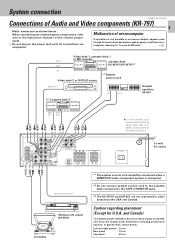
...connected when a KENWOOD audio component system is larger than , shown below . computer referring to , or greater than that indicated on the socket at the rear of the unit. Caution regarding placement (Except for U.S.A. System connection KR-897/KR-797 (En) Connections of Audio and Video components (KR-797) 5 Make ...Do not connect up a power source which is connected. *2 Do not connect system control cord to the cassette deck connected to the instruction manuals of the related components. 3 Do not plug in other areas than the USA and Canada. Left and right panels : 10 cm Rear...
...connected when a KENWOOD audio component system is larger than , shown below . computer referring to , or greater than that indicated on the socket at the rear of the unit. Caution regarding placement (Except for U.S.A. System connection KR-897/KR-797 (En) Connections of Audio and Video components (KR-797) 5 Make ...Do not connect up a power source which is connected. *2 Do not connect system control cord to the cassette deck connected to the instruction manuals of the related components. 3 Do not plug in other areas than the USA and Canada. Left and right panels : 10 cm Rear...
User Manual
Page 7
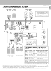
...Center speaker Powerd (8Ω ~ 16Ω) sub-woofer Speaker system A (8Ω ~ 16Ω) R L ·ª ·ª ª· KR-897/KR-797 (En) 7 * Connect the speakers for use in amp. L+ SPEAKERS B (8-16Њ) CENTER LINE IN MAIN IN (SPEAKERS B) L RR SURROUND MAIN IN... 50/60Hz UNSWITCHED *1 Power amplifier KM-897 *1 For the operation of the power amplifier (KM-897), refer to the instruction manual of speakers for ...
...Center speaker Powerd (8Ω ~ 16Ω) sub-woofer Speaker system A (8Ω ~ 16Ω) R L ·ª ·ª ª· KR-897/KR-797 (En) 7 * Connect the speakers for use in amp. L+ SPEAKERS B (8-16Њ) CENTER LINE IN MAIN IN (SPEAKERS B) L RR SURROUND MAIN IN... 50/60Hz UNSWITCHED *1 Power amplifier KM-897 *1 For the operation of the power amplifier (KM-897), refer to the instruction manual of speakers for ...
User Manual
Page 11
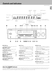
..., Input display, Preset channel display, Surround mode display TUNED indicator AUTO tuning/AUTO stereo reception indicator Display 2 34 56 7 8 9 0 AUDIO-VIDEO SURROUND RECEIVER KR-897 POWER ON/STANDBY PHONES SRS 3D SPEAKERS STANDBY 1 2 3 4 5 AUTO DIRECT MEMORY PRO LOGIC 3 STEREO 6 7 8 9 0 +10 TUNING BAND... the power cord from the remote control unit. Controls and indicators KR-897/KR-797 (En) TAPE 2 indicator N.B. In this jack. @AUTO key Press to select the tuning mode from the auto tuning and manual tuning modes.( Press and hold the DISPLAY key for the insuffi-...
..., Input display, Preset channel display, Surround mode display TUNED indicator AUTO tuning/AUTO stereo reception indicator Display 2 34 56 7 8 9 0 AUDIO-VIDEO SURROUND RECEIVER KR-897 POWER ON/STANDBY PHONES SRS 3D SPEAKERS STANDBY 1 2 3 4 5 AUTO DIRECT MEMORY PRO LOGIC 3 STEREO 6 7 8 9 0 +10 TUNING BAND... the power cord from the remote control unit. Controls and indicators KR-897/KR-797 (En) TAPE 2 indicator N.B. In this jack. @AUTO key Press to select the tuning mode from the auto tuning and manual tuning modes.( Press and hold the DISPLAY key for the insuffi-...
User Manual
Page 12
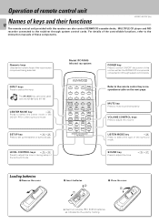
.... MUTE key Press to set up the balance or surround play. SOUND key Press to the instruction manuals of keys and their functions 12 The remote control unit provided with the KR-897 and KR-797. INPUT keys Press to select the center mode in the DOLBY PRO LOGIC surround mode. CENTER MODE...it through system control cords. LEVEL CONTROL keys %¢ Press to adjust the tone or during setup of this unit as well as the KENWOOD components connected to the recieiver through system control cords. VOLUME CONTROL keys Press to the remote control key correspondence table on the next page. Model...
.... MUTE key Press to set up the balance or surround play. SOUND key Press to the instruction manuals of keys and their functions 12 The remote control unit provided with the KR-897 and KR-797. INPUT keys Press to select the center mode in the DOLBY PRO LOGIC surround mode. CENTER MODE...it through system control cords. LEVEL CONTROL keys %¢ Press to adjust the tone or during setup of this unit as well as the KENWOOD components connected to the recieiver through system control cords. VOLUME CONTROL keys Press to the remote control key correspondence table on the next page. Model...
User Manual
Page 14
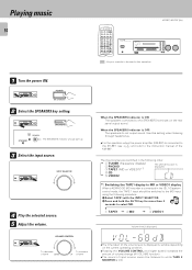
...4 CD 5 VIDEO2 CD *1: Switching the TAPE1 display to MD or VIDEO1 display When a KENWOOD MD recorder is connected to the KR-897, see 7 and refer to the instruction manual of input source cannot be listened to be switched to the MD input using the following procedure.... POWER ON/STANDBY 2 Select the SPEAKERS key setting. Note 1 TAPE1 2 MD 3 VIDEO1 Volume level is OFF: The speakers do not output sound. Playing music 14 KR-897/KR-797 (En) 1 2 3 POWER 4 5 6 0 7 8 9 +10 DISK SKIP 7 A/B +100 AUTO 1 ¡ VIDEO1 TAPE1 TUNER 2 6 BAND 4 ¢ P.CALL CD...
...4 CD 5 VIDEO2 CD *1: Switching the TAPE1 display to MD or VIDEO1 display When a KENWOOD MD recorder is connected to the KR-897, see 7 and refer to the instruction manual of input source cannot be listened to be switched to the MD input using the following procedure.... POWER ON/STANDBY 2 Select the SPEAKERS key setting. Note 1 TAPE1 2 MD 3 VIDEO1 Volume level is OFF: The speakers do not output sound. Playing music 14 KR-897/KR-797 (En) 1 2 3 POWER 4 5 6 0 7 8 9 +10 DISK SKIP 7 A/B +100 AUTO 1 ¡ VIDEO1 TAPE1 TUNER 2 6 BAND 4 ¢ P.CALL CD...
User Manual
Page 17
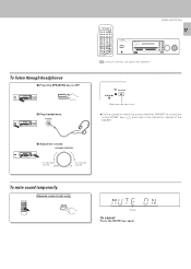
To listen through headphones 1 Press the SPEAKERS key to the instruction manual of the KM-897. 3 Adjust the volume. SPEAKERS 2 Plug headphones. SOURCE DIRECT P.CALL INPUT SELECTOR VOLUME CONTROL DOWN UP SPEAKERS : Keys or ... DOWN To increase UP volume To mute sound temporarily Remote control unit only MUTE M U T E ɹOçN Blinks To cancel Press the MUTE key again. PHONES KR-897/KR-797 (En) 1 2 3 POWER 4 5 6 0 7 8 9 +10 DISK SKIP 7 A/B +100 AUTO 1 ¡ VIDEO1 TAPE1 TUNER 2 6 BAND 4 ¢ P.CALL CD PHONO TAPE2 VIDEO2 MONITOR AV AUX ...
To listen through headphones 1 Press the SPEAKERS key to the instruction manual of the KM-897. 3 Adjust the volume. SPEAKERS 2 Plug headphones. SOURCE DIRECT P.CALL INPUT SELECTOR VOLUME CONTROL DOWN UP SPEAKERS : Keys or ... DOWN To increase UP volume To mute sound temporarily Remote control unit only MUTE M U T E ɹOçN Blinks To cancel Press the MUTE key again. PHONES KR-897/KR-797 (En) 1 2 3 POWER 4 5 6 0 7 8 9 +10 DISK SKIP 7 A/B +100 AUTO 1 ¡ VIDEO1 TAPE1 TUNER 2 6 BAND 4 ¢ P.CALL CD PHONO TAPE2 VIDEO2 MONITOR AV AUX ...
User Manual
Page 18
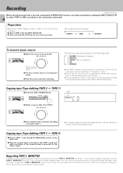
... the TAPE 2 MONITOR key lets you connect a graphic equalizer, turn the TAPE 2 MONITOR key ON. Recording KR-897/KR-797 (En) When recording sound with a recorder component of KENWOOD, synchro recording is not possible the VIDEO1 or MD input to this unit's TAPE 2 MONITOR terminals. Each press... switches the display. 1 TAPE1 2 MD 3 VIDEO1 To record a music source 1 Select the source to the operating manual ...
... the TAPE 2 MONITOR key lets you connect a graphic equalizer, turn the TAPE 2 MONITOR key ON. Recording KR-897/KR-797 (En) When recording sound with a recorder component of KENWOOD, synchro recording is not possible the VIDEO1 or MD input to this unit's TAPE 2 MONITOR terminals. Each press... switches the display. 1 TAPE1 2 MD 3 VIDEO1 To record a music source 1 Select the source to the operating manual ...
User Manual
Page 19
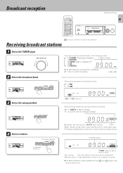
....) Frequency display - - AUTO DIRECT MEMORY 4 Select a station. Lights Select manual tuning when noise interferes due to AUTO (auto tuning). Auto tuning : The next station found is tuned. INPUT SELECTOR 2 Select the broadcast band. Broadcast reception KR-897/KR-797 (En) 1 2 3 POWER 4 5 6 0 7 8 9 +10 DISK SKIP 7 A/B +100 AUTO 1 ¡ VIDEO1 TAPE1 TUNER 2 6 BAND 4 ¢ P.CALL CD...
....) Frequency display - - AUTO DIRECT MEMORY 4 Select a station. Lights Select manual tuning when noise interferes due to AUTO (auto tuning). Auto tuning : The next station found is tuned. INPUT SELECTOR 2 Select the broadcast band. Broadcast reception KR-897/KR-797 (En) 1 2 3 POWER 4 5 6 0 7 8 9 +10 DISK SKIP 7 A/B +100 AUTO 1 ¡ VIDEO1 TAPE1 TUNER 2 6 BAND 4 ¢ P.CALL CD...

User Manual
Page 29
...the building, as practical. NOTE: This equipment has been tested and found to correct the interference by one or more of the FCC Rules. KR-897/KR-797 (En) 29 Remote control unit Symptom Remote control operation is completed. Consult the dealer or an experienced radio / TV technician for a Class...is too far away from that to Part 15 of the following measures: -- Cause Remedy ÷ Batteries are expressly approved in the instruction manual. nection". 45 ÷ Place the tape(s) or CD in accordance with the limits for help. nent to be operated does not contain the...
...the building, as practical. NOTE: This equipment has been tested and found to correct the interference by one or more of the FCC Rules. KR-897/KR-797 (En) 29 Remote control unit Symptom Remote control operation is completed. Consult the dealer or an experienced radio / TV technician for a Class...is too far away from that to Part 15 of the following measures: -- Cause Remedy ÷ Batteries are expressly approved in the instruction manual. nection". 45 ÷ Place the tape(s) or CD in accordance with the limits for help. nent to be operated does not contain the...
