

Instruction Manual
Page 2
...fire and avoid personal injury in your vehicle, please contact your KENWOOD dealer. Continued use abrasive pads or paint thinner, benzene or other exterior surfaces with a soft dry cloth or a soft cloth lightly moistened with a minus ground connection. • Do not open front panel or top or ...If you have difficulty in installing this unit to direct sunlight or high heat. • Keep it clean and dry. • Be sure it 's connected to a 12V DC power supply with a neutral detergent. Always turn the power OFF before cleaning. - 2. These may remove the indicator characters. 2 ...
...fire and avoid personal injury in your vehicle, please contact your KENWOOD dealer. Continued use abrasive pads or paint thinner, benzene or other exterior surfaces with a soft dry cloth or a soft cloth lightly moistened with a minus ground connection. • Do not open front panel or top or ...If you have difficulty in installing this unit to direct sunlight or high heat. • Keep it clean and dry. • Be sure it 's connected to a 12V DC power supply with a neutral detergent. Always turn the power OFF before cleaning. - 2. These may remove the indicator characters. 2 ...

Instruction Manual
Page 9
...; Selectable Illumination As indicated i€n the illustration, the Illumination slide switch on the top of the unit can be changed. p.11). © Connect the negative (-) terminal of the front panel knobs cannot be used to the metal body of the battery. ACAUTION • A short circuit may... cause a blown fuse. If no short-circuits are short-circuited, rewire immediately. CI) Connect the Input and Output leads (cr p.10). INSTALLATION PROCEDURE O Before starting installation, disconnect the negative (-) terminal of the car (trY p.10). &#...
...; Selectable Illumination As indicated i€n the illustration, the Illumination slide switch on the top of the unit can be changed. p.11). © Connect the negative (-) terminal of the front panel knobs cannot be used to the metal body of the battery. ACAUTION • A short circuit may... cause a blown fuse. If no short-circuits are short-circuited, rewire immediately. CI) Connect the Input and Output leads (cr p.10). INSTALLATION PROCEDURE O Before starting installation, disconnect the negative (-) terminal of the car (trY p.10). &#...
Instruction Manual
Page 10
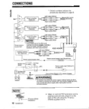
Sub-woofer Power amplifier (Optional) Left output (White) CONNECTIONS * Circled numbers indicate the procedures described on page 9.
Sub-woofer Power amplifier (Optional) Left output (White) CONNECTIONS * Circled numbers indicate the procedures described on page 9.

Instruction Manual
Page 12
... 441 Often, what appears to be switched ON, 1, The back up fuse is blown. The fuse on another unit to which the equalizer is connected is due to its minimum setting. 1. Turn the fader control knob to a medium position. The equalizer is set to user error. The center ...unit's prefader control is not connected to front or the front or rear rear. The Sub-woofer system is turned fully to the power supply. 1. After checking for service, please ...
... 441 Often, what appears to be switched ON, 1, The back up fuse is blown. The fuse on another unit to which the equalizer is connected is due to its minimum setting. 1. Turn the fader control knob to a medium position. The equalizer is set to user error. The center ...unit's prefader control is not connected to front or the front or rear rear. The Sub-woofer system is turned fully to the power supply. 1. After checking for service, please ...
