
Instruction Manual
Page 1
... obtain the best performance from your new electronic graphic equalizer. Model KGC-4042A Serial number ©PRINTED IN JAPAN B64 - 0229 • 00 (W. For your KENWOOD dealer for information or service on the warranty card, and in the space provided below, Refer to read through this instruction manual. Familiarity with installation and operation procedures will help you call upon...
... obtain the best performance from your new electronic graphic equalizer. Model KGC-4042A Serial number ©PRINTED IN JAPAN B64 - 0229 • 00 (W. For your KENWOOD dealer for information or service on the warranty card, and in the space provided below, Refer to read through this instruction manual. Familiarity with installation and operation procedures will help you call upon...

Instruction Manual
Page 2
...unit in installing this unit to direct sunlight or high heat. • Keep it clean and dry. • Be sure it is fastened securely and not exposed to the unit. NOTE • If you smell or see smoke, disconnect the unit immediately and consult your KENWOOD dealer.... SAFETY PRECAUTIONS AWARNING 4+,1 To prevent fire and avoid personal injury in case of accidents. • When extending the power supply or ground lead, avoid short circuits by using 0.75mm2 (AWG18) or larger automotive grade cable. •...
...unit in installing this unit to direct sunlight or high heat. • Keep it clean and dry. • Be sure it is fastened securely and not exposed to the unit. NOTE • If you smell or see smoke, disconnect the unit immediately and consult your KENWOOD dealer.... SAFETY PRECAUTIONS AWARNING 4+,1 To prevent fire and avoid personal injury in case of accidents. • When extending the power supply or ground lead, avoid short circuits by using 0.75mm2 (AWG18) or larger automotive grade cable. •...

Instruction Manual
Page 4
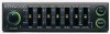
... level and cut-off frequency of five frequency bands centered around 50 i Hz, 200 Hz, 800 Hz, 3.2 kHz and 12.8 kHz. FEATURES A▪ • Graphic equalizer (p.5) i Allows level adjustment of your subwoofers. • Fader (p.7) Allows you begin
... level and cut-off frequency of five frequency bands centered around 50 i Hz, 200 Hz, 800 Hz, 3.2 kHz and 12.8 kHz. FEATURES A▪ • Graphic equalizer (p.5) i Allows level adjustment of your subwoofers. • Fader (p.7) Allows you begin

Instruction Manual
Page 5
... by up to -18 dB, the 800 Hz, 3.2 kHz and 12.8 kHz bands by up to 12 dB.) To lower level IP- Press the Graphic equalizer button. (The Graphic equalizer level knob indicator will go out indicating that the output sound has been adjusted with the graphic... Level adjustments To increase level II. Slide up the Graphic equalizer level knob for the frequency band you wish to adjust. (You can lower the 50 Hz and 200 Hz bands by up , indicating that the graphic equalizer has been turned off.) OFF KENWOOD GRAP.mlo. .152P-41-4-4.2A WO = = 17.I ON To...
... by up to -18 dB, the 800 Hz, 3.2 kHz and 12.8 kHz bands by up to 12 dB.) To lower level IP- Press the Graphic equalizer button. (The Graphic equalizer level knob indicator will go out indicating that the output sound has been adjusted with the graphic... Level adjustments To increase level II. Slide up the Graphic equalizer level knob for the frequency band you wish to adjust. (You can lower the 50 Hz and 200 Hz bands by up , indicating that the graphic equalizer has been turned off.) OFF KENWOOD GRAP.mlo. .152P-41-4-4.2A WO = = 17.I ON To...
Instruction Manual
Page 6
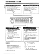
... the sub-woofers' level infinitely until sub-woofer output is off.) NOTE • When the sub-woofer system is turned on, it will cease.) OFF KENWOOD PHI O a= SUL .W0g . SO Sub-woofer system ON - 40 20 100 1000 Hz Front/Rear output characteristics curve Sub-woofer output will automatically cut -off...
... the sub-woofers' level infinitely until sub-woofer output is off.) NOTE • When the sub-woofer system is turned on, it will cease.) OFF KENWOOD PHI O a= SUL .W0g . SO Sub-woofer system ON - 40 20 100 1000 Hz Front/Rear output characteristics curve Sub-woofer output will automatically cut -off...
Instruction Manual
Page 8
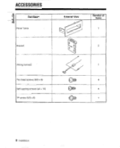
Pan head screws (M3 x 6) Self-tapping screws (04 x 16) TP screw (M3 x 6) External View o 0 ,:..;:, c 0 O 0 4)11)10' 4 101110 X3)1E1 Number of Items 1 2 1 4 4 1 8 Installation ACCESSORIES Part Name Panel frame i----Bracket Wiring names;
Pan head screws (M3 x 6) Self-tapping screws (04 x 16) TP screw (M3 x 6) External View o 0 ,:..;:, c 0 O 0 4)11)10' 4 101110 X3)1E1 Number of Items 1 2 1 4 4 1 8 Installation ACCESSORIES Part Name Panel frame i----Bracket Wiring names;

Instruction Manual
Page 9
.... If no short-circuits are found, replace the fuse with one having the same rating (see indication in fuse box). • Check that could also cause a fire, Check the wiring carefully and, if any wires are in the car (r? o. 0 Pc ILLUM GRN Lf ...is a serious problem that unconnected wires or connectors are short-circuited, rewire immediately. Installation 9 INSTALLATION PROCEDURE O Before starting installation, disconnect the negative (-) terminal of the battery. C) Connect the Ground lead {Black) to the metal body of the front panel knobs cannot be used to select either...
.... If no short-circuits are found, replace the fuse with one having the same rating (see indication in fuse box). • Check that could also cause a fire, Check the wiring carefully and, if any wires are in the car (r? o. 0 Pc ILLUM GRN Lf ...is a serious problem that unconnected wires or connectors are short-circuited, rewire immediately. Installation 9 INSTALLATION PROCEDURE O Before starting installation, disconnect the negative (-) terminal of the battery. C) Connect the Ground lead {Black) to the metal body of the front panel knobs cannot be used to select either...
Instruction Manual
Page 10
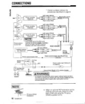
Sub-woofer Power amplifier (Optional) Left output (White) CONNECTIONS * Circled numbers indicate the procedures described on page 9.
Sub-woofer Power amplifier (Optional) Left output (White) CONNECTIONS * Circled numbers indicate the procedures described on page 9.
Instruction Manual
Page 11
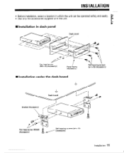
INSTALLATION • Before installation, select a location in dash panel O1O OO _s i Dash panel vd Pan head screw (M3 x 6) (Accessory) Panel frame (Accessory) ---- 416 Self-tapping screws (4, 4 x16) (Accessory) • Installation under the dash board Dash board Bracket (Accessory) II so 01• Pan head screw (M3x6) (Accessory) 0:fiticop[,08 Self-tapping screws (04 x 16) (Accessory) Installation 11 INInstallation in which the unit can be operated safely and easily. • Use only the accessories supplied with the unit.
INSTALLATION • Before installation, select a location in dash panel O1O OO _s i Dash panel vd Pan head screw (M3 x 6) (Accessory) Panel frame (Accessory) ---- 416 Self-tapping screws (4, 4 x16) (Accessory) • Installation under the dash board Dash board Bracket (Accessory) II so 01• Pan head screw (M3x6) (Accessory) 0:fiticop[,08 Self-tapping screws (04 x 16) (Accessory) Installation 11 INInstallation in which the unit can be operated safely and easily. • Use only the accessories supplied with the unit.

Instruction Manual
Page 12
...supply. 1. The equalizer is not connected to which the equalizer is connected is blown. 2. After checking for service, please consult the following table. Turn the fader control knob to a medium position. Connect the power supply. There is no sub-woofers installed. Make sure that.... 1. Set the center unit fader to the front/rear balance you prefer. The center unit's prefader control is set to user error. TROUBLESHOOTING GUIDE 441 Often, what appears to be switched ON, 1, The back up fuse is blown. Before calling for short circuits, replace the blown...
...supply. 1. The equalizer is not connected to which the equalizer is connected is blown. 2. After checking for service, please consult the following table. Turn the fader control knob to a medium position. Connect the power supply. There is no sub-woofers installed. Make sure that.... 1. Set the center unit fader to the front/rear balance you prefer. The center unit's prefader control is set to user error. TROUBLESHOOTING GUIDE 441 Often, what appears to be switched ON, 1, The back up fuse is blown. Before calling for short circuits, replace the blown...

Instruction Manual
Page 13
SPECIFICATIONS Specifications subject to 60 kHz 0 dB General Operating Voltage Max. Audio Characteristics Input Impedance Output Impedance Signal to Noise Ratio T.H.D Frequency Response (-3 dB) Gain 10 i(S/ 600 100 dB 0.01% 10 Hz to change without notice In re. Current Consumption Installed Size Weight 14.4 V (11-16 V)... 0.18 A 89 x 25 x 130 mm (3-1/2 x 1 x 5-1/8 in) 0.4_1cg (0.9 Ib) 13 Equalizer Equalizer Center Frequencies Equalization Range 50 Hz, 200 Hz, 800 Hz, 3.2 kHz, 12.8 ...
SPECIFICATIONS Specifications subject to 60 kHz 0 dB General Operating Voltage Max. Audio Characteristics Input Impedance Output Impedance Signal to Noise Ratio T.H.D Frequency Response (-3 dB) Gain 10 i(S/ 600 100 dB 0.01% 10 Hz to change without notice In re. Current Consumption Installed Size Weight 14.4 V (11-16 V)... 0.18 A 89 x 25 x 130 mm (3-1/2 x 1 x 5-1/8 in) 0.4_1cg (0.9 Ib) 13 Equalizer Equalizer Center Frequencies Equalization Range 50 Hz, 200 Hz, 800 Hz, 3.2 kHz, 12.8 ...


