Instruction Manual
Page 1
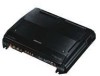
... will help you call upon your Kenwood dealer for information or service on the warranty card, and in the spaces designated on the product. KAC-X10D CLASS D MONO POWER AMPLIFIER 7 page 2-7 INSTRUCTION MANUAL AMPLIFICATEUR MONO CLASSE D 7 page 8-13 MODE D'EMPLOI AMPLIFICADOR DE POTENCIA CLASE D MONOFÓNICO 7 página 14-19 MANUAL DE INSTRUCCIONES Take the time to the model and serial numbers whenever you obtain the best performance...
... will help you call upon your Kenwood dealer for information or service on the warranty card, and in the spaces designated on the product. KAC-X10D CLASS D MONO POWER AMPLIFIER 7 page 2-7 INSTRUCTION MANUAL AMPLIFICATEUR MONO CLASSE D 7 page 8-13 MODE D'EMPLOI AMPLIFICADOR DE POTENCIA CLASE D MONOFÓNICO 7 página 14-19 MANUAL DE INSTRUCCIONES Take the time to the model and serial numbers whenever you obtain the best performance...
Instruction Manual
Page 2
... input power ratings that are going to be connected should be short-circuited. • When a speaker output contacts ground. • When the unit malfunctions and a DC signal is sent to the speaker output. • When the internal temperature is high and unit won't operate. • When a ground wire of the center unit (cassette receiver, CD receiver, etc.) or this unit directly from the battery. When the protection function is triggered, the Power indicator...
... input power ratings that are going to be connected should be short-circuited. • When a speaker output contacts ground. • When the unit malfunctions and a DC signal is sent to the speaker output. • When the internal temperature is high and unit won't operate. • When a ground wire of the center unit (cassette receiver, CD receiver, etc.) or this unit directly from the battery. When the protection function is triggered, the Power indicator...
Instruction Manual
Page 3
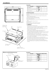
... : 15 mm or more) ■ Remote controller (Optional accessory) Mounting bracket Remote controller Self-tapping screw (ø2.6 × 12 mm) Accessories Part name Remote cable (6.0 m : 19.7 ft) External View Number of the units. 4.Connect the speaker wires. 5.Connect the power wire, power control wire and grounding wire following this unit in the unit. 7.Attach the unit. 8.Install the remote controller. (Optional accessory) 9.Connect the negative - Installation 318 mm 258 mm Ø6 Hexagon socket head cap screw (M4 × 12 mm) Dressing...
... : 15 mm or more) ■ Remote controller (Optional accessory) Mounting bracket Remote controller Self-tapping screw (ø2.6 × 12 mm) Accessories Part name Remote cable (6.0 m : 19.7 ft) External View Number of the units. 4.Connect the speaker wires. 5.Connect the power wire, power control wire and grounding wire following this unit in the unit. 7.Attach the unit. 8.Install the remote controller. (Optional accessory) 9.Connect the negative - Installation 318 mm 258 mm Ø6 Hexagon socket head cap screw (M4 × 12 mm) Dressing...

Instruction Manual
Page 4
... nearby the battery's positive terminal. Sharing the negative wire of the speaker or grounding speaker wires to the left. Remote cable (6.0 m : 19.7 ft) Remote controller 4 English CENTER UNIT (CD receiver, etc.) Power control wire 2CAUTION • If sound is not output normally, immediately turn power off before changing the setting of any switch. • If the fuse blows, check wires for shorts, then replace the fuse with one of the car can cause this unit to appropriate speaker connectors separately...
... nearby the battery's positive terminal. Sharing the negative wire of the speaker or grounding speaker wires to the left. Remote cable (6.0 m : 19.7 ft) Remote controller 4 English CENTER UNIT (CD receiver, etc.) Power control wire 2CAUTION • If sound is not output normally, immediately turn power off before changing the setting of any switch. • If the fuse blows, check wires for shorts, then replace the fuse with one of the car can cause this unit to appropriate speaker connectors separately...

Instruction Manual
Page 5
... the LINE OUT FILTER switch ON. Setting the Slave amplifier 1. Set the LPF frequency and ISF. 3. Adjust the INPUT SENSIVITY. • To adjust the Slave amplifier to the same volume as the Master amplifier, adjust the INPUT SENSIVITY to 0.2 V (max.). 2CAUTION • Before connecting the remote controller cables, always turn the Bass boost level knob all the way to the left. 40 CENTER UNIT (CD receiver, etc.) Power control wire Master amplifier Extension wire* * Commercially available parts RCA cable* Remote cable Remote controller RCA cable* 40 Slave amplifier 40 Slave amplifier...
... the LINE OUT FILTER switch ON. Setting the Slave amplifier 1. Set the LPF frequency and ISF. 3. Adjust the INPUT SENSIVITY. • To adjust the Slave amplifier to the same volume as the Master amplifier, adjust the INPUT SENSIVITY to 0.2 V (max.). 2CAUTION • Before connecting the remote controller cables, always turn the Bass boost level knob all the way to the left. 40 CENTER UNIT (CD receiver, etc.) Power control wire Master amplifier Extension wire* * Commercially available parts RCA cable* Remote cable Remote controller RCA cable* 40 Slave amplifier 40 Slave amplifier...
Instruction Manual
Page 6
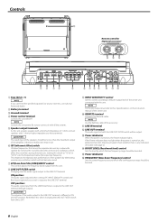
... of 1 ohm, connect speakers with this unit. 8 LINE OUT FILTER switch Changing over the audio signal output to these terminals. 2CAUTION The rated input of the center unit. 0 REMOTE terminal Connects the Remote cable. OFF position: The audio signal input from this unit. NOTE For the pre-output level, refer to the LINE OUT terminal is any indication of trouble. (See page 2) $ BOOST LEVEL (Bass boost level) control Sets the level by which the low frequency range should be boosted. % Power idndicator ^ FREQUENCY (Bass boost frequency) control Sets the center frequency around which...
... of 1 ohm, connect speakers with this unit. 8 LINE OUT FILTER switch Changing over the audio signal output to these terminals. 2CAUTION The rated input of the center unit. 0 REMOTE terminal Connects the Remote cable. OFF position: The audio signal input from this unit. NOTE For the pre-output level, refer to the LINE OUT terminal is any indication of trouble. (See page 2) $ BOOST LEVEL (Bass boost level) control Sets the level by which the low frequency range should be boosted. % Power idndicator ^ FREQUENCY (Bass boost frequency) control Sets the center frequency around which...

Instruction Manual
Page 7
... and fixing the cause of the short, replace the fuse. • Adjust the control correctly referring to . • Connect the Remote Cable securely and correctly. English 7 SOLUTION • Connect the input (or output) cables. • Check connections by a screw in your unit may be the result of the terminals and wires well. • Connect the speaker wire again so that it is distorted.) The Remote Controller does not function. CEA-2006 RMS Watts per channel @ 4 ohms...
... and fixing the cause of the short, replace the fuse. • Adjust the control correctly referring to . • Connect the Remote Cable securely and correctly. English 7 SOLUTION • Connect the input (or output) cables. • Check connections by a screw in your unit may be the result of the terminals and wires well. • Connect the speaker wire again so that it is distorted.) The Remote Controller does not function. CEA-2006 RMS Watts per channel @ 4 ohms...


