
Instruction Manual
Page 1
... spaces designated on the product. Model KGC-4042A Serial number ©PRINTED IN JAPAN B64 - 0229 • 00 (W. Familiarity with installation and operation procedures will help you call upon your KENWOOD dealer for information or service on the warranty card, and in the space provided below, Refer to read through this instruction manual. KGC-4042A GRAPHIC MANUAL EGAUSEUR GRAPHIQUE MODE D'EMPLOI...
... spaces designated on the product. Model KGC-4042A Serial number ©PRINTED IN JAPAN B64 - 0229 • 00 (W. Familiarity with installation and operation procedures will help you call upon your KENWOOD dealer for information or service on the warranty card, and in the space provided below, Refer to read through this instruction manual. KGC-4042A GRAPHIC MANUAL EGAUSEUR GRAPHIQUE MODE D'EMPLOI...

Instruction Manual
Page 2
... see smoke, disconnect the unit immediately and consult your KENWOOD dealer. SAFETY PRECAUTIONS AWARNING 4+,1 To prevent fire and avoid personal injury in case of accidents. • When extending the power supply or ground lead, avoid short circuits by using 0.75mm2 (AWG18) or larger automotive grade cable. &#...8226; Check to be sure that no metal objects (tools, needles, coins) are left inside the unit. • If you have difficulty in installing this unit to direct sunlight or high heat...
... see smoke, disconnect the unit immediately and consult your KENWOOD dealer. SAFETY PRECAUTIONS AWARNING 4+,1 To prevent fire and avoid personal injury in case of accidents. • When extending the power supply or ground lead, avoid short circuits by using 0.75mm2 (AWG18) or larger automotive grade cable. &#...8226; Check to be sure that no metal objects (tools, needles, coins) are left inside the unit. • If you have difficulty in installing this unit to direct sunlight or high heat...

Instruction Manual
Page 4
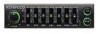
... you to adjust the balance of five frequency bands centered around 50 i Hz, 200 Hz, 800 Hz, 3.2 kHz and 12.8 kHz. FEATURES A▪ • Graphic equalizer (p.5) i Allows level adjustment of front and rear speakers. • SeleCtable illumination (p.9) Allows illumination color to be switched between green and orange. 4 Before you begin
... you to adjust the balance of five frequency bands centered around 50 i Hz, 200 Hz, 800 Hz, 3.2 kHz and 12.8 kHz. FEATURES A▪ • Graphic equalizer (p.5) i Allows level adjustment of front and rear speakers. • SeleCtable illumination (p.9) Allows illumination color to be switched between green and orange. 4 Before you begin

Instruction Manual
Page 5
... and 12.8 kHz bands by up to -12 dB.) Your new Graphic equalizer 5 Press the Graphic equalizer button. (The Graphic equalizer level knob indicator will light up, indicating that the graphic equalizer has been turned off.) OFF KENWOOD GRAP.mlo. .152P-41-4-4.2A WO = = 17.I ON To turn ...the graphic equalizer ON 10- GRAPHIC EQUALIZER To turn the graphic equalizer OFF 0- Slide up the Graphic equalizer level knob for the frequency band you...
... and 12.8 kHz bands by up to -12 dB.) Your new Graphic equalizer 5 Press the Graphic equalizer button. (The Graphic equalizer level knob indicator will light up, indicating that the graphic equalizer has been turned off.) OFF KENWOOD GRAP.mlo. .152P-41-4-4.2A WO = = 17.I ON To turn ...the graphic equalizer ON 10- GRAPHIC EQUALIZER To turn the graphic equalizer OFF 0- Slide up the Graphic equalizer level knob for the frequency band you...
Instruction Manual
Page 6
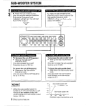
... sub-woofer system OFF ► Press the Sub-woofer button. (The Sub-woofer level knob and the Sub-woofer frequency knob indicators will cease.) OFF KENWOOD PHI O a= SUL .W0g .
... sub-woofer system OFF ► Press the Sub-woofer button. (The Sub-woofer level knob and the Sub-woofer frequency knob indicators will cease.) OFF KENWOOD PHI O a= SUL .W0g .
Instruction Manual
Page 8
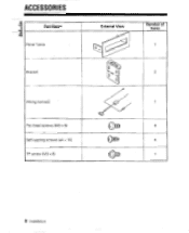
Pan head screws (M3 x 6) Self-tapping screws (04 x 16) TP screw (M3 x 6) External View o 0 ,:..;:, c 0 O 0 4)11)10' 4 101110 X3)1E1 Number of Items 1 2 1 4 4 1 8 Installation ACCESSORIES Part Name Panel frame i----Bracket Wiring names;
Pan head screws (M3 x 6) Self-tapping screws (04 x 16) TP screw (M3 x 6) External View o 0 ,:..;:, c 0 O 0 4)11)10' 4 101110 X3)1E1 Number of Items 1 2 1 4 4 1 8 Installation ACCESSORIES Part Name Panel frame i----Bracket Wiring names;

Instruction Manual
Page 9
...wiring carefully and, if any wires are in the car (r? ACAUTION • A short circuit may cause a blown fuse. Installation 9 o. 0 Pc ILLUM GRN Lf ORG Green => Orange NOTE • The color of the battery. A short circuit is a serious problem that unconnected wires or connectors are short-circuited, rewire immediately. If no short-circuits are found, replace... of the front panel knobs cannot be used to the metal body of the battery. INSTALLATION PROCEDURE O Before starting installation, disconnect the negative (-) terminal of the car (trY p.10). ® Connect the...
...wiring carefully and, if any wires are in the car (r? ACAUTION • A short circuit may cause a blown fuse. Installation 9 o. 0 Pc ILLUM GRN Lf ORG Green => Orange NOTE • The color of the battery. A short circuit is a serious problem that unconnected wires or connectors are short-circuited, rewire immediately. If no short-circuits are found, replace... of the front panel knobs cannot be used to the metal body of the battery. INSTALLATION PROCEDURE O Before starting installation, disconnect the negative (-) terminal of the car (trY p.10). ® Connect the...
Instruction Manual
Page 10
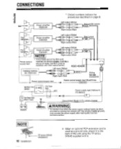
CONNECTIONS * Circled numbers indicate the procedures described on page 9. Sub-woofer Power amplifier (Optional) Left output (White)
CONNECTIONS * Circled numbers indicate the procedures described on page 9. Sub-woofer Power amplifier (Optional) Left output (White)
Instruction Manual
Page 11
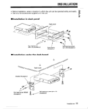
INInstallation in which the unit can be operated safely and easily. • Use only the accessories supplied with the unit. INSTALLATION • Before installation, select a location in dash panel O1O OO _s i Dash panel vd Pan head screw (M3 x 6) (Accessory) Panel frame (Accessory) ---- 416 Self-tapping screws (4, 4 x16) (Accessory) • Installation under the dash board Dash board Bracket (Accessory) II so 01• Pan head screw (M3x6) (Accessory) 0:fiticop[,08 Self-tapping screws (04 x 16) (Accessory) Installation 11
INInstallation in which the unit can be operated safely and easily. • Use only the accessories supplied with the unit. INSTALLATION • Before installation, select a location in dash panel O1O OO _s i Dash panel vd Pan head screw (M3 x 6) (Accessory) Panel frame (Accessory) ---- 416 Self-tapping screws (4, 4 x16) (Accessory) • Installation under the dash board Dash board Bracket (Accessory) II so 01• Pan head screw (M3x6) (Accessory) 0:fiticop[,08 Self-tapping screws (04 x 16) (Accessory) Installation 11

Instruction Manual
Page 12
...malfunction is ON with no sound from 1 The fader is set to its minimum setting. 1. Be sure the new fuse has the required capacity. 2. Set the center unit fader to the front/rear balance you prefer. The equalizer is blown. Sound is not heard from any speakers. 1....is no sub-woofers installed. Before calling for short circuits, replace the blown fuse. A speaker, power or precut connection is blown. 2. The fuse on another unit to which the equalizer is connected is loose. 2. The Sub-woofer system is due to user error. TROUBLESHOOTING GUIDE 441 Often, what ...
...malfunction is ON with no sound from 1 The fader is set to its minimum setting. 1. Be sure the new fuse has the required capacity. 2. Set the center unit fader to the front/rear balance you prefer. The equalizer is blown. Sound is not heard from any speakers. 1....is no sub-woofers installed. Before calling for short circuits, replace the blown fuse. A speaker, power or precut connection is blown. 2. The fuse on another unit to which the equalizer is connected is loose. 2. The Sub-woofer system is due to user error. TROUBLESHOOTING GUIDE 441 Often, what ...

Instruction Manual
Page 13
Equalizer Equalizer Center Frequencies Equalization Range 50 Hz, 200 Hz, 800 Hz, 3.2 kHz, 12.8 kHz 50 Hz, 200 Hz: -18 to +18 dB 800 Hz, 3.2 kHz, 12.8 kHz: -12 to +... Output Gain Cut-off Slope 30 to 150 Hz (variable) --to change without notice In re. Current Consumption Installed Size Weight 14.4 V (11-16 V) 0.18 A 89 x 25 x 130 mm (3-1/2 x 1 x 5-1/8 in) 0.4_1cg (0.9 Ib) 13 SPECIFICATIONS Specifications subject to +10 dB 12 dB/oct. Audio Characteristics Input Impedance Output Impedance Signal to Noise Ratio T.H.D Frequency...
Equalizer Equalizer Center Frequencies Equalization Range 50 Hz, 200 Hz, 800 Hz, 3.2 kHz, 12.8 kHz 50 Hz, 200 Hz: -18 to +18 dB 800 Hz, 3.2 kHz, 12.8 kHz: -12 to +... Output Gain Cut-off Slope 30 to 150 Hz (variable) --to change without notice In re. Current Consumption Installed Size Weight 14.4 V (11-16 V) 0.18 A 89 x 25 x 130 mm (3-1/2 x 1 x 5-1/8 in) 0.4_1cg (0.9 Ib) 13 SPECIFICATIONS Specifications subject to +10 dB 12 dB/oct. Audio Characteristics Input Impedance Output Impedance Signal to Noise Ratio T.H.D Frequency...

Service Manual
Page 1
GRAPHIC EQUALIZER KGC-4042A SERVICE MANUAL REVISED S/No. 10700001~ Panel ass'y (A64-0071-08) C 2001-8 PRINTED IN JAPAN B51-7838-00 (4) 3395 Knob (EQ) (K24-0700-08) Knob (FAD) (K29-5541-08) Trim plate (A21-0474-03) Screw set (N99-1543-08) Bracket (J21-3693-04) Knob (SUB) (K24-0710-08) Metallic cabinet (A01-2568-08) RCA pin cord (OUT, SUB) (E30-3649-08) RCA pin cord (OUT, R) (E30-3648-08) RCA pin cord (OUT, F) (E30-3647-08) RCA pin cord (IN) (E30-3646-08) Power connection cord (E30-3654-08) RCA pin cap (F29-0049-05)
GRAPHIC EQUALIZER KGC-4042A SERVICE MANUAL REVISED S/No. 10700001~ Panel ass'y (A64-0071-08) C 2001-8 PRINTED IN JAPAN B51-7838-00 (4) 3395 Knob (EQ) (K24-0700-08) Knob (FAD) (K29-5541-08) Trim plate (A21-0474-03) Screw set (N99-1543-08) Bracket (J21-3693-04) Knob (SUB) (K24-0710-08) Metallic cabinet (A01-2568-08) RCA pin cord (OUT, SUB) (E30-3649-08) RCA pin cord (OUT, R) (E30-3648-08) RCA pin cord (OUT, F) (E30-3647-08) RCA pin cord (IN) (E30-3646-08) Power connection cord (E30-3654-08) RCA pin cap (F29-0049-05)
Service Manual
Page 2
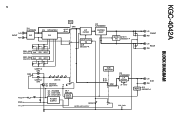
FILTER IC2 NJM2068MD BUFFER A.M.P SWITCHING TR Q8,9 2SC3327-A MUTE Q10,11 TR 2SC3327-A Lch FRONT Rch Lch REAR Rch BLOCK DIAGRAM ACC GND P. FILTER 30~150Hz Lch SUB Rch Q12 MUTE 2SC3327-A PRE. C SW3 LAMP1,2 (OR) LAMP3,4 (GR) LED1-5 Q1 2SC4640 Q2 2SC1741A +B Q3 2SC2060 Q4 DTA114ES Q5 DTC114ES POWER SUPPLY Q6,7 2SA1782 MUTE DRIVE LED6,7 METER LED SUPPLY SUB WOOFER ON OFF SW2 IC3 NJM2068MD L.P. KGC-4042A 2 Lch INPUT Rch IC4 NJM2060M ISO IC5 UPC4570G2 EQ Q201-205 2SC2712 Lch Q251-255 2SC2712 Rch EQ B.P.F EQ B.P.F EQ SW1 OFF ON H.P. GND
FILTER IC2 NJM2068MD BUFFER A.M.P SWITCHING TR Q8,9 2SC3327-A MUTE Q10,11 TR 2SC3327-A Lch FRONT Rch Lch REAR Rch BLOCK DIAGRAM ACC GND P. FILTER 30~150Hz Lch SUB Rch Q12 MUTE 2SC3327-A PRE. C SW3 LAMP1,2 (OR) LAMP3,4 (GR) LED1-5 Q1 2SC4640 Q2 2SC1741A +B Q3 2SC2060 Q4 DTA114ES Q5 DTC114ES POWER SUPPLY Q6,7 2SA1782 MUTE DRIVE LED6,7 METER LED SUPPLY SUB WOOFER ON OFF SW2 IC3 NJM2068MD L.P. KGC-4042A 2 Lch INPUT Rch IC4 NJM2060M ISO IC5 UPC4570G2 EQ Q201-205 2SC2712 Lch Q251-255 2SC2712 Rch EQ B.P.F EQ B.P.F EQ SW1 OFF ON H.P. GND

Service Manual
Page 3
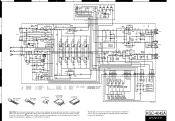
... IC5 Address 3I 4I 4H 3G 4I Ref. Q7 Q8 Q9 Q10 Q11 Q12 Address 3B 4D 5D 4B 4B 3C 7 Refer to the schematic diagram for the values of resistors and capacitors. 4 E LAMP2 LAMP1 D A B C D PC BOARD (Component side view) ELECTRIC UNIT 1 MAIN PWB E EQ ON/OFF PWB A P.CON GND +B CN15.... Q201 Q202 Q203 Q204 Q205 Q251 Q252 Q253 Q254 Q255 Address 5J 5J 5J 5J 5J 4G 4G 4G 4G 4G Refer to the schematic diagram for the values of resistors and capacitors. No. No. No.
... IC5 Address 3I 4I 4H 3G 4I Ref. Q7 Q8 Q9 Q10 Q11 Q12 Address 3B 4D 5D 4B 4B 3C 7 Refer to the schematic diagram for the values of resistors and capacitors. 4 E LAMP2 LAMP1 D A B C D PC BOARD (Component side view) ELECTRIC UNIT 1 MAIN PWB E EQ ON/OFF PWB A P.CON GND +B CN15.... Q201 Q202 Q203 Q204 Q205 Q251 Q252 Q253 Q254 Q255 Address 5J 5J 5J 5J 5J 4G 4G 4G 4G 4G Refer to the schematic diagram for the values of resistors and capacitors. No. No. No.
Service Manual
Page 4
... (exposed parts are as measured with a high impedance voltmeter. Indicates safety critical components. VR2(7/7) SUBWOOFER LEVEL LED1 LED2 LED3 LED4 LED5 LED6 LED7 VR2(1/7) 2 VR2(2/7) 3 VR2(3/7) 4 VR2(4/7) 5 VR2(5/7) 6 6 NJM2068MD 2SC1741A(R) DTA114ES 2SC2712(GR) B UPC4570G2 5 NJM2060M 8 2SC2060 DTC114ES B EC E BC E 8 C 14 4 1 7 1 50 200 800 3.2K 12.8K KGC-4042A 7 CAUTION: For continued safety, replace safety...
... (exposed parts are as measured with a high impedance voltmeter. Indicates safety critical components. VR2(7/7) SUBWOOFER LEVEL LED1 LED2 LED3 LED4 LED5 LED6 LED7 VR2(1/7) 2 VR2(2/7) 3 VR2(3/7) 4 VR2(4/7) 5 VR2(5/7) 6 6 NJM2068MD 2SC1741A(R) DTA114ES 2SC2712(GR) B UPC4570G2 5 NJM2060M 8 2SC2060 DTC114ES B EC E BC E 8 C 14 4 1 7 1 50 200 800 3.2K 12.8K KGC-4042A 7 CAUTION: For continued safety, replace safety...
Service Manual
Page 5
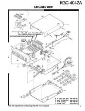
A φ2.6x5 (F-Tap) BLK : N85-2605-45 B φ3x5 (Bi-Tap) BLK : N86-3005-45 C φ3x4 (Bi-Tap) : N09-2630-08 D φ3x4.5 RIVET : N29-0053-05 7 B D 721 723 C F1 731 D 22 20 18 17 16 15 3 702 25 Parts with exploded view numbers larger than 700 are not supplied. A 24x2 EXPLODED VIEW B KGC-4042A B 30 B 1 4 50 200 800 3.2K 12.8K FREQ LEVEL VR2-1 VR2-2 VR2-3 VR2-4 VR2-5 VR2-6 VR2-7 LED1 LED2 LED3 LED4 LED5 LED6 LED7 LAMP4 23 LAMP2 705 26 A 2 704 706 28x7 A LAMP1 LAMP3 23 FADER 3 VR1 SUB C SW1 722 27 1 B ILLUM 724 SW3 SW2 EQ.
A φ2.6x5 (F-Tap) BLK : N85-2605-45 B φ3x5 (Bi-Tap) BLK : N86-3005-45 C φ3x4 (Bi-Tap) : N09-2630-08 D φ3x4.5 RIVET : N29-0053-05 7 B D 721 723 C F1 731 D 22 20 18 17 16 15 3 702 25 Parts with exploded view numbers larger than 700 are not supplied. A 24x2 EXPLODED VIEW B KGC-4042A B 30 B 1 4 50 200 800 3.2K 12.8K FREQ LEVEL VR2-1 VR2-2 VR2-3 VR2-4 VR2-5 VR2-6 VR2-7 LED1 LED2 LED3 LED4 LED5 LED6 LED7 LAMP4 23 LAMP2 705 26 A 2 704 706 28x7 A LAMP1 LAMP3 23 FADER 3 VR1 SUB C SW1 722 27 1 B ILLUM 724 SW3 SW2 EQ.
Service Manual
Page 6
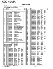
... B46-0100-50 WARRANTY CARD - B64-0229-00 INSTRUCTION MANUAL 15 3B E30-3646-08 CORD WITH PLUG (IN...-2605-45 N86-3005-45 N09-2630-08 N29-0053-05 SCREW SET FLAT HEAD TAPTITE SCREW BINDING HEAD TAPTITE SCREW TAPTITE SCREW PUSH RIVET ...WIRING HARNESS PIN ASS'Y WIRING HARNESS indicates safety critical components. H25-1101-04 PROTECTION BAG (150X500) - KGC-4042A ∗New Parts PARTS LIST Parts without Parts No. are not supplied. Les articles non mentionnes dans le Parts No. ne sont pas fournis. werden nicht geliefert. d e dw Parts No. Ref. d e Parts No. tion KGC-4042A...
... B46-0100-50 WARRANTY CARD - B64-0229-00 INSTRUCTION MANUAL 15 3B E30-3646-08 CORD WITH PLUG (IN...-2605-45 N86-3005-45 N09-2630-08 N29-0053-05 SCREW SET FLAT HEAD TAPTITE SCREW BINDING HEAD TAPTITE SCREW TAPTITE SCREW PUSH RIVET ...WIRING HARNESS PIN ASS'Y WIRING HARNESS indicates safety critical components. H25-1101-04 PROTECTION BAG (150X500) - KGC-4042A ∗New Parts PARTS LIST Parts without Parts No. are not supplied. Les articles non mentionnes dans le Parts No. ne sont pas fournis. werden nicht geliefert. d e dw Parts No. Ref. d e Parts No. tion KGC-4042A...
Service Manual
Page 7
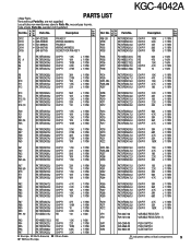
...33K J 1/10W CHIP R 150K J 1/10W VARIABLE RESISTOR VARIABLE RESISTOR(1-7) PUSH SWITCH PUSH SWITCH SLIDE SWITCH indicates safety critical components. 9 KGC-4042A ∗New Parts PARTS LIST Parts without Parts No. dw CN12 ∗ E41-0223-08 CN13 ∗ E39-0458-08 CN13 ∗ E41-0090-05 CN14 ∗ E39-0457...-08 CN15 E40-3677-05 Description PIN ASS'Y WIRING HARNESS PIN ASS'Y WIRING HARNESS SOCKET FOR PIN ASS'Y Des- AN tina- d e Parts No. ne sont pas fournis. Ref. tion dw R98 ,99 RK73FB2A104J R100 RK73FB2A332J R101 ...
...33K J 1/10W CHIP R 150K J 1/10W VARIABLE RESISTOR VARIABLE RESISTOR(1-7) PUSH SWITCH PUSH SWITCH SLIDE SWITCH indicates safety critical components. 9 KGC-4042A ∗New Parts PARTS LIST Parts without Parts No. dw CN12 ∗ E41-0223-08 CN13 ∗ E39-0458-08 CN13 ∗ E41-0090-05 CN14 ∗ E39-0457...-08 CN15 E40-3677-05 Description PIN ASS'Y WIRING HARNESS PIN ASS'Y WIRING HARNESS SOCKET FOR PIN ASS'Y Des- AN tina- d e Parts No. ne sont pas fournis. Ref. tion dw R98 ,99 RK73FB2A104J R100 RK73FB2A332J R101 ...

Service Manual
Page 8
..., Kwai Fong, N.T., Hong Kong KENWOOD ELECTRONICS GULF FZE P.O. d e dw Parts No. Description Des- For this reason specifications may be changed without notice. werden nicht geliefert. No. are not supplied. KENWOOD ELECTRONICS (THAILAND) CO., LTD. 2019 New Pechburi Road, Bangkapi, Huaykwang, Bangkok, 10320 Thailand KENWOOD ELECTRONICS SINGAPORE PTE. KGC-4042A ∗New Parts PARTS LIST Parts without Parts No. Box 22745, 2201...
..., Kwai Fong, N.T., Hong Kong KENWOOD ELECTRONICS GULF FZE P.O. d e dw Parts No. Description Des- For this reason specifications may be changed without notice. werden nicht geliefert. No. are not supplied. KENWOOD ELECTRONICS (THAILAND) CO., LTD. 2019 New Pechburi Road, Bangkapi, Huaykwang, Bangkok, 10320 Thailand KENWOOD ELECTRONICS SINGAPORE PTE. KGC-4042A ∗New Parts PARTS LIST Parts without Parts No. Box 22745, 2201...


