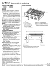
Dimension Guide
Page 1
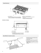
...) actual width C. D E. 22" (55.9 cm) F. 3 8.4 cm) G 1.4 cm) Page 1 of combustion and ventilation air. Specifications subject to change without requiring removal of the cooktop. Gas inlet is located 1⁷⁄₈" (4.8 cm) from strong draft areas, such as windows, doors and strong heating vents or...change materials and specifications without consulting the serving gas supplier. The model/ serial rating plate located on the left -hand side of the cooktop burner base. Electrical: q A 120 volt, 60 Hz, AC only, 15-amp, fused electrical circuit is required. See "Electrical ...
...) actual width C. D E. 22" (55.9 cm) F. 3 8.4 cm) G 1.4 cm) Page 1 of combustion and ventilation air. Specifications subject to change without requiring removal of the cooktop. Gas inlet is located 1⁷⁄₈" (4.8 cm) from strong draft areas, such as windows, doors and strong heating vents or...change materials and specifications without consulting the serving gas supplier. The model/ serial rating plate located on the left -hand side of the cooktop burner base. Electrical: q A 120 volt, 60 Hz, AC only, 15-amp, fused electrical circuit is required. See "Electrical ...

Dimension Guide
Page 2
...11.261c.m9 )cfmor) or zero4c7le⁷⁄a₈"ra(n1c2e1.6 cm) for 36" (91.4 cm) and 48" (121.9 cm) cooktops. For complete details, see Installation our products, we reserve the right to gas opening cutout H. 6⁷⁄₈" (16.1 cm) gas ...or the supply line can be located in this area on both sides of the cooktop to the side wall or other combustible material above the cooktop Isfuirnfsa*tc*aeN6ll".iOn(1Tg5E.a2: Ircfambna)gcisekrwheaqoluol iidrsedcaobfnoosrvt4eru8ct"ht(ee1d2c1oo.f9oakcctmoo)pmc,bofuooskllttoiobwplestmhaneadteracrinoagol ...
...11.261c.m9 )cfmor) or zero4c7le⁷⁄a₈"ra(n1c2e1.6 cm) for 36" (91.4 cm) and 48" (121.9 cm) cooktops. For complete details, see Installation our products, we reserve the right to gas opening cutout H. 6⁷⁄₈" (16.1 cm) gas ...or the supply line can be located in this area on both sides of the cooktop to the side wall or other combustible material above the cooktop Isfuirnfsa*tc*aeN6ll".iOn(1Tg5E.a2: Ircfambna)gcisekrwheaqoluol iidrsedcaobfnoosrvt4eru8ct"ht(ee1d2c1oo.f9oakcctmoo)pmc,bofuooskllttoiobwplestmhaneadteracrinoagol ...
Installation Instruction
Page 2
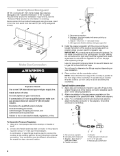
... the State of Massachusetts, the following installation instructions apply: ■ Installations and repairs must not exceed 3 feet. 2 If a gas leak is the safety alert symbol. COOKTOP SAFETY Your safety and the safety of others . WARNING You can kill or hurt you smell gas" instructions. WHAT TO DO IF YOU SMELL GAS...
... the State of Massachusetts, the following installation instructions apply: ■ Installations and repairs must not exceed 3 feet. 2 If a gas leak is the safety alert symbol. COOKTOP SAFETY Your safety and the safety of others . WARNING You can kill or hurt you smell gas" instructions. WHAT TO DO IF YOU SMELL GAS...
Installation Instruction
Page 3
... away from the countertop by its side or rear flanges. ■ The gas and electric supply should be installed above the cooktop. ■ The cooktop should be used will not discolor, delaminate or sustain other damage. Tools Needed ■ Adjustable wrench ■ Tape measure &#... To order, see the "Gas Conversions" section. In Canada, the installation of combustion and ventilation air. ■ It is not recommended that a microwave hood combination be mounted above the cooktop. ■ It is the installer's responsibility to make sure that are included. ■ Gas ...
... away from the countertop by its side or rear flanges. ■ The gas and electric supply should be installed above the cooktop. ■ The cooktop should be used will not discolor, delaminate or sustain other damage. Tools Needed ■ Adjustable wrench ■ Tape measure &#... To order, see the "Gas Conversions" section. In Canada, the installation of combustion and ventilation air. ■ It is not recommended that a microwave hood combination be mounted above the cooktop. ■ It is the installer's responsibility to make sure that are included. ■ Gas ...
Installation Instruction
Page 4
...⁷⁄₈" (120.8 cm) actual width C. Grounded 3-prong outlet should be located on the underside of the cooktop burner base) Side View of Cooktop A B C G E F A. 27¾" (70.5 cm) B. 1¼" (3.2 cm) C. 7 18.8 cm) D. D 4 D E. 22" (55.9 cm) F. 3 8.4 cm) G 1.4 cm) Gas and Electric Connection Locations B C A A.... clearance from enclosure sidewall B. 10" (25.4 cm) min. Gas supply line should be located in from the back of the cooktop burner base and 4⁷⁄₈" (12.4 cm) in this area on rear or side walls, or the supply line can come up...
...⁷⁄₈" (120.8 cm) actual width C. Grounded 3-prong outlet should be located on the underside of the cooktop burner base) Side View of Cooktop A B C G E F A. 27¾" (70.5 cm) B. 1¼" (3.2 cm) C. 7 18.8 cm) D. D 4 D E. 22" (55.9 cm) F. 3 8.4 cm) G 1.4 cm) Gas and Electric Connection Locations B C A A.... clearance from enclosure sidewall B. 10" (25.4 cm) min. Gas supply line should be located in from the back of the cooktop burner base and 4⁷⁄₈" (12.4 cm) in this area on rear or side walls, or the supply line can come up...
Installation Instruction
Page 5
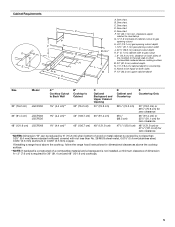
... J. 22¹⁄₄" (56.5 cm) cabinet cutout depth K. 2" (5.1 cm) cabinet side to countertop O. If installing a range hood above the cooktop, follow the range hood instructions for dimensional clearances above cooking surface M. 24" (61.0 cm) cabinet depth N. 7¹⁄₄" (18.4 cm) cabinet...Notch to be equal on both sides P. 13" (33.0 cm) upper cabinet depth Size Model 30" (76.2 cm) JGCP430 A** Cooktop Cutout to Back Wall B* Cooktop to countertop G 1.9 cm) back of wood or metal cabinet is required for zero clearance *NOTES: Dimension "B" can be reduced by not...
... J. 22¹⁄₄" (56.5 cm) cabinet cutout depth K. 2" (5.1 cm) cabinet side to countertop O. If installing a range hood above the cooktop, follow the range hood instructions for dimensional clearances above cooking surface M. 24" (61.0 cm) cabinet depth N. 7¹⁄₄" (18.4 cm) cabinet...Notch to be equal on both sides P. 13" (33.0 cm) upper cabinet depth Size Model 30" (76.2 cm) JGCP430 A** Cooktop Cutout to Back Wall B* Cooktop to countertop G 1.9 cm) back of wood or metal cabinet is required for zero clearance *NOTES: Dimension "B" can be reduced by not...
Installation Instruction
Page 6
...8224; tape. †®TEFLON is a registered trademark of local codes, with a different gas without consulting the serving gas supplier. This cooktop is equipped with all local codes and ordinances. A time-delay fuse or circuit breaker is correctly grounded. ■ The wiring diagrams are ...size can be provided. ■ Electronic ignition systems operate within wide voltage limits, but proper grounding and polarity are provided with this cooktop be obtained from the gas specified on the model/serial rating plate for use an extension cord. IMPORTANT: Leak testing of a ...
...8224; tape. †®TEFLON is a registered trademark of local codes, with a different gas without consulting the serving gas supplier. This cooktop is equipped with all local codes and ordinances. A time-delay fuse or circuit breaker is correctly grounded. ■ The wiring diagrams are ...size can be provided. ■ Electronic ignition systems operate within wide voltage limits, but proper grounding and polarity are provided with this cooktop be obtained from the gas specified on the model/serial rating plate for use an extension cord. IMPORTANT: Leak testing of a ...
Installation Instruction
Page 7
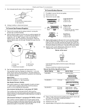
...Supply Pressure Testing Gas supply pressure for each 1,000 ft (304.8 m) above the manifold pressure shown on your cooktop. The parts shipped with this cooktop must be isolated from the gas supply piping system during any pressure testing of that allows ease of opening and ... its individual shutoff valve must be equipped with your model ordered. Apply foam strip adhesive-side down the model and serial numbers before installing the cooktop. Flexible metal appliance connector: ■ If local codes permit, a new CSA design-certified, 4 - 5 ft (122 - 152.4 cm) long 1.6 cm) or &#...
...Supply Pressure Testing Gas supply pressure for each 1,000 ft (304.8 m) above the manifold pressure shown on your cooktop. The parts shipped with this cooktop must be isolated from the gas supply piping system during any pressure testing of that allows ease of opening and ... its individual shutoff valve must be equipped with your model ordered. Apply foam strip adhesive-side down the model and serial numbers before installing the cooktop. Flexible metal appliance connector: ■ If local codes permit, a new CSA design-certified, 4 - 5 ft (122 - 152.4 cm) long 1.6 cm) or &#...
Installation Instruction
Page 8
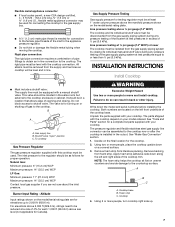
... Examples of pipe fittings must be wrench-tightened. To Assemble Pressure Regulator: 1. Using 2 or more people, stand the cooktop on ordering. Connect the flexible stainless steel connector to the adapters. Shown following illustration). 2. Do not allow the regulator to... requirements. Securely tighten all gas connections. Your connection may require a backguard. Tighten both adapters. 3. Check that the front edge of the cooktop burner base and in a position where you can result in the "Location Requirements" section for information on its side or back. 2. A...
... Examples of pipe fittings must be wrench-tightened. To Assemble Pressure Regulator: 1. Using 2 or more people, stand the cooktop on ordering. Connect the flexible stainless steel connector to the adapters. Shown following illustration). 2. Do not allow the regulator to... requirements. Securely tighten all gas connections. Your connection may require a backguard. Tighten both adapters. 3. Check that the front edge of the cooktop burner base and in a position where you can result in the "Location Requirements" section for information on its side or back. 2. A...
Installation Instruction
Page 9
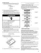
...pilots. Incorrect B. Correct Electrical Shock Hazard Plug into a grounded 3 prong outlet. 5. Plug into a grounded 3 prong outlet. When the cooktop control knob is open " position. ■ Check that burner caps are properly positioned on an approved noncorrosive leak-detection solution. If you ...Slide tray toward the back until the flame is lit or the knob is parallel to Off. Check Operation of air in the "Complete Installation" section. 6. If your cooktop. 9 Place burner caps on griddle models) The griddle is lit it stops. See "Check Operation of the ...
...pilots. Incorrect B. Correct Electrical Shock Hazard Plug into a grounded 3 prong outlet. 5. Plug into a grounded 3 prong outlet. When the cooktop control knob is open " position. ■ Check that burner caps are properly positioned on an approved noncorrosive leak-detection solution. If you ...Slide tray toward the back until the flame is lit or the knob is parallel to Off. Check Operation of air in the "Complete Installation" section. 6. If your cooktop. 9 Place burner caps on griddle models) The griddle is lit it stops. See "Check Operation of the ...
Installation Instruction
Page 10
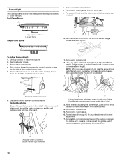
... screw to adjust. A A. Console attachment screws 6. Remove the control knob. 15. Upper (simmer) flame B. Unplug cooktop or disconnect power. 2. Pull cooktop forward to expose the control console screws on the single output valves. NOTE: When you want to increase flame height. Dual...screwdriver to reduce flame height. Disconnect wiring from the valve stem. 9. Single flame burner adjustment screw (on left side of the cooktop burner base. 5. Lower flame Single Flame Burner 10. Tighten screw to adjust the flame height. Replace the round gasket. 16. ...
... screw to adjust. A A. Console attachment screws 6. Remove the control knob. 15. Upper (simmer) flame B. Unplug cooktop or disconnect power. 2. Pull cooktop forward to expose the control console screws on the single output valves. NOTE: When you want to increase flame height. Dual...screwdriver to reduce flame height. Disconnect wiring from the valve stem. 9. Single flame burner adjustment screw (on left side of the cooktop burner base. 5. Lower flame Single Flame Burner 10. Tighten screw to adjust the flame height. Replace the round gasket. 16. ...
Installation Instruction
Page 11
... spring retainer from Natural gas to LP gas must hook over the spring retainer so the "LP" is flush with top of the cooktop. For a proper fit, the flange of the control console must be done by pushing against the flat side of the control console.... a wrench, turning the access cap counterclockwise. 2. If connected to do so can result in death, explosion, or fire. Gasket C. Flush with the top edge of cooktop 20. A B A. Replace the control knobs. 23. Gas pressure regulator C D. A C A. Gas supply line 2. Front lip of a qualified person include: licensed ...
... spring retainer from Natural gas to LP gas must hook over the spring retainer so the "LP" is flush with top of the cooktop. For a proper fit, the flange of the control console must be done by pushing against the flat side of the control console.... a wrench, turning the access cap counterclockwise. 2. If connected to do so can result in death, explosion, or fire. Gasket C. Flush with the top edge of cooktop 20. A B A. Replace the control knobs. 23. Gas pressure regulator C D. A C A. Gas supply line 2. Front lip of a qualified person include: licensed ...
Installation Instruction
Page 12
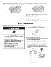
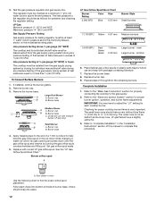
...Surface Burners 1. Burner cap B B. Burner base C. Complete Installation 1. Refer to the "Electronic Ignition System" section for properly connecting the cooktop to or less than ½ psi (3.5 kPa). The small inner cone should be disconnected from the gas supply piping system by turning...blue flame ¼" (0.64 cm) to find the exact orifice spud placement. Line pressure testing above ½ psi gauge (14" WCP) The cooktop and its individual manual shutoff valve during any pressure testing of ½ psi (3.5 kPa). Remove burner cap. 3. Large Dual Burner A A. ...
...Surface Burners 1. Burner cap B B. Burner base C. Complete Installation 1. Refer to the "Electronic Ignition System" section for properly connecting the cooktop to or less than ½ psi (3.5 kPa). The small inner cone should be disconnected from the gas supply piping system by turning...blue flame ¼" (0.64 cm) to find the exact orifice spud placement. Line pressure testing above ½ psi gauge (14" WCP) The cooktop and its individual manual shutoff valve during any pressure testing of ½ psi (3.5 kPa). Remove burner cap. 3. Large Dual Burner A A. ...
Installation Instruction
Page 13
... Orifice Spud/Hood Chart." Access cap B. Gas pressure regulator C D. LP position 3. Line pressure testing above ½ psi gauge (14" WCP) The cooktop and its individual manual shutoff valve during any pressure testing of that system at the spring retainer to find the exact orifice spud placement. Natural...orifice spud in excess of a 7 mm nut driver to or less than ½ psi (3.5 kPa). Replace burner cap. 9. To cooktop B. Unplug cooktop or disconnect power. Snap the spring retainer back into gas opening and press down onto the gas orifice spud and remove by closing its ...
... Orifice Spud/Hood Chart." Access cap B. Gas pressure regulator C D. LP position 3. Line pressure testing above ½ psi gauge (14" WCP) The cooktop and its individual manual shutoff valve during any pressure testing of that system at the spring retainer to find the exact orifice spud placement. Natural...orifice spud in excess of a 7 mm nut driver to or less than ½ psi (3.5 kPa). Replace burner cap. 9. To cooktop B. Unplug cooktop or disconnect power. Snap the spring retainer back into gas opening and press down onto the gas orifice spud and remove by closing its ...
Installation Instruction
Page 14
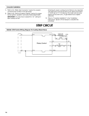
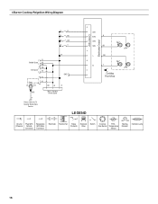
..."LO" setting for proper burner ignition, operation, and burner flame adjustments. LP gas flames have to the "Electronic Ignition System" section for each cooktop burner. Refer to "Complete Installation" in the "Installation Instructions" section of this manual to ½" (1.3 cm) long. IMPORTANT: You may ...have a slightly yellow tip. 3. The outer cone is very important. STRIP CIRCUIT Griddle 120V Control Wiring Diagram To Cooktop Stand-Alone R P2-1 P1-1 OR/W 1320W/120V OR/W Lamp 120V BU W Rotary Control P1-3 W P1-4 V W RTD W WV V W P2-6 P1...
..."LO" setting for proper burner ignition, operation, and burner flame adjustments. LP gas flames have to the "Electronic Ignition System" section for each cooktop burner. Refer to "Complete Installation" in the "Installation Instructions" section of this manual to ½" (1.3 cm) long. IMPORTANT: You may ...have a slightly yellow tip. 3. The outer cone is very important. STRIP CIRCUIT Griddle 120V Control Wiring Diagram To Cooktop Stand-Alone R P2-1 P1-1 OR/W 1320W/120V OR/W Lamp 120V BU W Rotary Control P1-3 W P1-4 V W RTD W WV V W P2-6 P1...
Installation Instruction
Page 15
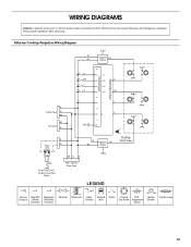
... View Ground Plug With Receptacle (Chassis) Female With Male Connector Connector Electrode Transformer Relay Contacts Solenoid Valve Switch Cooktop RTD - Verify proper operation after servicing. 6 Burner Cooktop Reignition Wiring Diagram W BU Reignition BU Module Electrodes Output Control Input G RR R BR RY RG 2 1 SW1 SW2 R SW3 SW4 OR R R Griddle Spare W BK 4 3 L Y N G BK Grill...
... View Ground Plug With Receptacle (Chassis) Female With Male Connector Connector Electrode Transformer Relay Contacts Solenoid Valve Switch Cooktop RTD - Verify proper operation after servicing. 6 Burner Cooktop Reignition Wiring Diagram W BU Reignition BU Module Electrodes Output Control Input G RR R BR RY RG 2 1 SW1 SW2 R SW3 SW4 OR R R Griddle Spare W BK 4 3 L Y N G BK Grill...
Installation Instruction
Page 16
4 Burner Cooktop Reignition Wiring Diagram Electrodes Output Control Input G R R R BU R BR R Y SW1 SW2 R SW3 SW4 BU 2 1 R Griddle Spare W BK BK Grill Spare W Power Cord L N R W BK W R GND R GND Main - Harness Power Spare L OR N Y 4 3 Cooktop Front View Power Cord Only To Cooktop Stand Alone Version LEGEND Ground Plug With Receptacle (Chassis) Female With Male Connector Connector Electrode Transformer Relay Contacts Solenoid Valve Switch Cooktop RTD - Gas Burner Temperature Sensor Heating Element Indicator Lamp 16
4 Burner Cooktop Reignition Wiring Diagram Electrodes Output Control Input G R R R BU R BR R Y SW1 SW2 R SW3 SW4 BU 2 1 R Griddle Spare W BK BK Grill Spare W Power Cord L N R W BK W R GND R GND Main - Harness Power Spare L OR N Y 4 3 Cooktop Front View Power Cord Only To Cooktop Stand Alone Version LEGEND Ground Plug With Receptacle (Chassis) Female With Male Connector Connector Electrode Transformer Relay Contacts Solenoid Valve Switch Cooktop RTD - Gas Burner Temperature Sensor Heating Element Indicator Lamp 16

Use and Care
Page 3
... or death. - WARNING You can be killed or seriously injured if you don't immediately follow the "What to potential hazards that you smell gas" instructions. 3 COOKTOP SAFETY Your safety and the safety of others . This symbol alerts you to do if you use a gas detector approved by UL or CSA. All...
... or death. - WARNING You can be killed or seriously injured if you don't immediately follow the "What to potential hazards that you smell gas" instructions. 3 COOKTOP SAFETY Your safety and the safety of others . This symbol alerts you to do if you use a gas detector approved by UL or CSA. All...
Use and Care
Page 4
.... Doing so may result from combustible materials, gasoline, and other reproductive harm. Be sure the cooktop is properly installed and grounded by a qualified technician. ■ This cooktop is equipped with a three-prong grounding plug for your protection against shock hazard and should be ...plugged directly into a properly grounded receptacle. Flammable materials should not be stored on the cooktop - State of California Proposition 65 Warnings: WARNING: This product contains one or more chemicals known to the State of California to...
.... Doing so may result from combustible materials, gasoline, and other reproductive harm. Be sure the cooktop is properly installed and grounded by a qualified technician. ■ This cooktop is equipped with a three-prong grounding plug for your protection against shock hazard and should be ...plugged directly into a properly grounded receptacle. Flammable materials should not be stored on the cooktop - State of California Proposition 65 Warnings: WARNING: This product contains one or more chemicals known to the State of California to...

Use and Care
Page 5
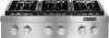
The cooktop you have some models) D. Commercial style die cast metal control knobs B. Left rear control knob B. Left front control knob C. Electric chrome griddle (on griddle models) ...
The cooktop you have some models) D. Commercial style die cast metal control knobs B. Left rear control knob B. Left front control knob C. Electric chrome griddle (on griddle models) ...

