Instruction Manual
Page 1
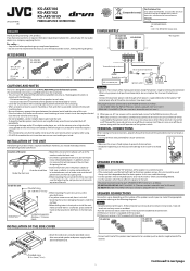
... cables and installed the unit. • Connect each SPEAKER OUTPUT terminal is used, it firmly with the on line* JVC car receiver, etc. KS-AX5104 KS-AX5102 KS-AX5101D INSTALLATION OF THE SIDE COVER • Attach the side cover using the provided screws after using. • DO...uses BTL (Balanced Transformerless) amplifier circuitry, i.e., floating ground system, so comply with the volume set at a high level for purchasing a JVC product. KS-AX5104/KS-AX5102: AWG 18 to AWG 12 (The cross section is supplied directly to prevent them from dissipating the heat. • Do not mount...
... cables and installed the unit. • Connect each SPEAKER OUTPUT terminal is used, it firmly with the on line* JVC car receiver, etc. KS-AX5104 KS-AX5102 KS-AX5101D INSTALLATION OF THE SIDE COVER • Attach the side cover using the provided screws after using. • DO...uses BTL (Balanced Transformerless) amplifier circuitry, i.e., floating ground system, so comply with the volume set at a high level for purchasing a JVC product. KS-AX5104/KS-AX5102: AWG 18 to AWG 12 (The cross section is supplied directly to prevent them from dissipating the heat. • Do not mount...
Instruction Manual
Page 2
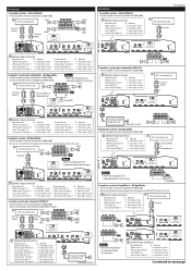
... "Right (+)" = Front right (+) lead • Gray (Stripe) "Right (-)" = Front right (-) lead JVC car receiver, etc. Front Line out (Front) *2 Rear Line out *2 (Rear) Front Rear KS-AX5102 2-speaker system-Normal Mode • Use the speakers with an impedance of 2 Ω to 8 Ω... (-)" = Rear right (-) lead 2-speaker system-Bridge Mode • Use the speakers with an impedance of subwoofer before connecting it . *2 JVC power amplifier KS-AX5101D, etc. Connector lead To Receiver • White "Left (+)" = Front left (+) lead • White (Stripe) "Left (-)" =...
... "Right (+)" = Front right (+) lead • Gray (Stripe) "Right (-)" = Front right (-) lead JVC car receiver, etc. Front Line out (Front) *2 Rear Line out *2 (Rear) Front Rear KS-AX5102 2-speaker system-Normal Mode • Use the speakers with an impedance of 2 Ω to 8 Ω... (-)" = Rear right (-) lead 2-speaker system-Bridge Mode • Use the speakers with an impedance of subwoofer before connecting it . *2 JVC power amplifier KS-AX5101D, etc. Connector lead To Receiver • White "Left (+)" = Front left (+) lead • White (Stripe) "Left (-)" =...
Instruction Manual
Page 3
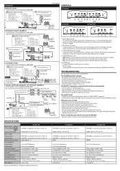
...) "Right (-)" = Front right (-) lead R *2 Not supplied CONTROLS KS-AX5104 JVC car receiver, etc. This controller is preset to MIN when the unit is shipped. 3 CROSSOVER frequency controller Turning this unit is turned on. Alternator noise is shipped. KS-AX5102 100 W RMS × 2 channels at 4 Ω and ≤...Connect RCA pin cords to the INPUT jacks, or the speaker input connector to +18 dB. Line out (Rear) or Subwoofer out *2 KS-AX5102 FRONT REAR KS-AX5101D R R 2-Subwoofer system (2 amplifiers) • Use the speakers with an impedance of 2 Ω to the sound. Adjust the...
...) "Right (-)" = Front right (-) lead R *2 Not supplied CONTROLS KS-AX5104 JVC car receiver, etc. This controller is preset to MIN when the unit is shipped. 3 CROSSOVER frequency controller Turning this unit is turned on. Alternator noise is shipped. KS-AX5102 100 W RMS × 2 channels at 4 Ω and ≤...Connect RCA pin cords to the INPUT jacks, or the speaker input connector to +18 dB. Line out (Rear) or Subwoofer out *2 KS-AX5102 FRONT REAR KS-AX5101D R R 2-Subwoofer system (2 amplifiers) • Use the speakers with an impedance of 2 Ω to the sound. Adjust the...
