Instruction Manual
Page 1
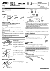
... on the number of the ignition switch. Model No. Serial No 1211MOHMDWKAYA EN © 2011 JVC KENWOOD Corporation * Not Supplied ACCESSORIES Φ4 × 20 mm (13/16 in.) ...4 KS-AX5102 KS-AX5101D KS-AX5104 To metallic body or chassis* (To an accessory terminal) Fuse* Φ3 × 8 ... cause a short circuit then replace the old fuse with one with the provided screw by the ignition switch. LVT2338-001A [K] KS-AX5104 KS-AX5102 KS-AX5101D POWER AMPLIFIER: Instructions ENGLISH Thank you for future reference. Retain this case, noise may cause an accident. • Run...
... on the number of the ignition switch. Model No. Serial No 1211MOHMDWKAYA EN © 2011 JVC KENWOOD Corporation * Not Supplied ACCESSORIES Φ4 × 20 mm (13/16 in.) ...4 KS-AX5102 KS-AX5101D KS-AX5104 To metallic body or chassis* (To an accessory terminal) Fuse* Φ3 × 8 ... cause a short circuit then replace the old fuse with one with the provided screw by the ignition switch. LVT2338-001A [K] KS-AX5104 KS-AX5102 KS-AX5101D POWER AMPLIFIER: Instructions ENGLISH Thank you for future reference. Retain this case, noise may cause an accident. • Run...
Instruction Manual
Page 2
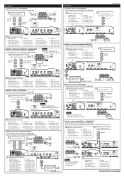
... • Gray (Stripe) "Right (-)" = Front right (-) lead JVC car receiver, etc. Speaker input connector. Line out *2 JVC car receiver, etc. KS-AX5104 4-speaker system-Normal Mode • Use the speakers with an impedance of 2 Ω to 8 Ω. Front Line out (Front) *2 Rear Line out *2 (Rear) Front Rear KS-AX5102 2-speaker system-Normal Mode • Use the...
... • Gray (Stripe) "Right (-)" = Front right (-) lead JVC car receiver, etc. Speaker input connector. Line out *2 JVC car receiver, etc. KS-AX5104 4-speaker system-Normal Mode • Use the speakers with an impedance of 2 Ω to 8 Ω. Front Line out (Front) *2 Rear Line out *2 (Rear) Front Rear KS-AX5102 2-speaker system-Normal Mode • Use the...
Instruction Manual
Page 3
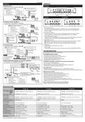
...system employs too many amplifiers. • Confirm the battery voltage (11 V to this position. SPECIFICATIONS Power Output • Normal Mode: KS-AX5104 70 W RMS × 4 channels at 4 Ω and ≤ 1% THD + N Signal-to-Noise Ratio Power Output &#... lead = Front left (-) lead • Gray "Right (+)" = Front right (+) lead • Gray (Stripe) "Right (-)" = Front right (-) lead R *2 Not supplied CONTROLS KS-AX5104 JVC car receiver, etc. KS-AX5102 100 W RMS × 2 channels at 4 Ω and ≤ 1% THD + N 80 dBA (reference: 1 W into 4 Ω) 150 W RMS × 2 ...
...system employs too many amplifiers. • Confirm the battery voltage (11 V to this position. SPECIFICATIONS Power Output • Normal Mode: KS-AX5104 70 W RMS × 4 channels at 4 Ω and ≤ 1% THD + N Signal-to-Noise Ratio Power Output &#... lead = Front left (-) lead • Gray "Right (+)" = Front right (+) lead • Gray (Stripe) "Right (-)" = Front right (-) lead R *2 Not supplied CONTROLS KS-AX5104 JVC car receiver, etc. KS-AX5102 100 W RMS × 2 channels at 4 Ω and ≤ 1% THD + N 80 dBA (reference: 1 W into 4 Ω) 150 W RMS × 2 ...