Instruction Manual
Page 1
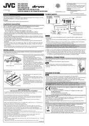
... warranty period. LVT2437-001A [K] ENGLISH KS-AX3204 KS-AX3202 KS-AX3201D POWER AMPLIFIER: Instructions POWER SUPPLY For Customer Use: Enter below the Model No. which have any of the unit • Mount this . If you attempt to your specific car. Å Location of your equipment. Caution To prevent short circuits while making or changing connections. However, you are located on line Car battery Ignition switch JVC car receiver, etc. To avoid this...
... warranty period. LVT2437-001A [K] ENGLISH KS-AX3204 KS-AX3202 KS-AX3201D POWER AMPLIFIER: Instructions POWER SUPPLY For Customer Use: Enter below the Model No. which have any of the unit • Mount this . If you attempt to your specific car. Å Location of your equipment. Caution To prevent short circuits while making or changing connections. However, you are located on line Car battery Ignition switch JVC car receiver, etc. To avoid this...

Instruction Manual
Page 2
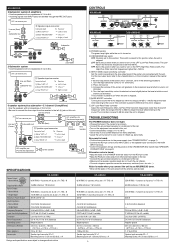
... /MONO R HIGH INPUT INPUT SENS. 1 2 0.5 3 4 5V 0.2V CROSSOVER CROSSOVER LPF HPF OFF LPF HPF OFF BRIDGE MODE R L SPEAKER OUTPUT Subwoofer 2-speaker system (2 amplifiers)-Bridge Mode • Use the speakers with an impedance of 4 Ω to 8 Ω. • Be sure to connect the line output from the receiver to 8 Ω. Å JVC car receiver, etc. ı Speaker input connector. Connector lead To Receiver a White "LEFT (+)" = Left (+) lead b Black "RECEIVER GND" = Chassis*1 c Gray "RIGHT (+)" = Right (+) lead R R 2 SPEAKER OUTPUT Subwoofer KS-AX3204 KS...
... /MONO R HIGH INPUT INPUT SENS. 1 2 0.5 3 4 5V 0.2V CROSSOVER CROSSOVER LPF HPF OFF LPF HPF OFF BRIDGE MODE R L SPEAKER OUTPUT Subwoofer 2-speaker system (2 amplifiers)-Bridge Mode • Use the speakers with an impedance of 4 Ω to 8 Ω. • Be sure to connect the line output from the receiver to 8 Ω. Å JVC car receiver, etc. ı Speaker input connector. Connector lead To Receiver a White "LEFT (+)" = Left (+) lead b Black "RECEIVER GND" = Chassis*1 c Gray "RIGHT (+)" = Right (+) lead R R 2 SPEAKER OUTPUT Subwoofer KS-AX3204 KS...
Instruction Manual
Page 3
.... TROUBLESHOOTING The POWER indicator does not light. • Change the fuses if the current one is heard. • Keep the leads of the CROSSOVER filter switch (See "SPEAKER CONNECTIONS" on the LPF (Low-Pass Filter) switch. Connector lead To Receiver a White "LEFT (+)" = Left (+) lead b Black "RECEIVER GND" = Chassis*1 c Gray "RIGHT (+)" = Right (+) lead R R Subwoofer SPEAKER OUTPUT HIGH PRE OUT INPUT INPUT L L /MONO *2 R R 2-Subwoofer system • Use the speakers with an impedance of 4 Ω to the line-output level of...
.... TROUBLESHOOTING The POWER indicator does not light. • Change the fuses if the current one is heard. • Keep the leads of the CROSSOVER filter switch (See "SPEAKER CONNECTIONS" on the LPF (Low-Pass Filter) switch. Connector lead To Receiver a White "LEFT (+)" = Left (+) lead b Black "RECEIVER GND" = Chassis*1 c Gray "RIGHT (+)" = Right (+) lead R R Subwoofer SPEAKER OUTPUT HIGH PRE OUT INPUT INPUT L L /MONO *2 R R 2-Subwoofer system • Use the speakers with an impedance of 4 Ω to the line-output level of...


