Instructions
Page 2
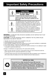
... 2. Avoid Improper installation and never position the unit where good ventilation is intended to alert the user to repair it yourself or remove the rear cover. In the event of electric shock. Do not attempt to the presence of time, be regulated in your local authorities, or the ... TO RAIN OR MOISTURE. Do not remove cover (or back). Changes or modifications not approved by JVC could void the warranty. * When you don't use this TV set for USA) This product has a High Intensity Discharge (HID) lamp that may be sure to persons. NOTICE (for a long period of ...
... 2. Avoid Improper installation and never position the unit where good ventilation is intended to alert the user to repair it yourself or remove the rear cover. In the event of electric shock. Do not attempt to the presence of time, be regulated in your local authorities, or the ... TO RAIN OR MOISTURE. Do not remove cover (or back). Changes or modifications not approved by JVC could void the warranty. * When you don't use this TV set for USA) This product has a High Intensity Discharge (HID) lamp that may be sure to persons. NOTICE (for a long period of ...
Instructions
Page 4
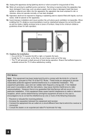
...and never position the unit where good ventilation is impossible. Reorient or relocate the receiving antenna. - Consult the dealer or an experienced radio/TV technician for a Class B digital device, pursuant to Part 15 of heat during lightning storms or when unused for long periods of the ...does not operate normally, or has been dropped. 15) Apparatus shall not be maintained between the equipment and receiver. - When installing this TV, distance recommendations must be exposed to which can radiate radio frequency energy and, if not installed and used in a corner on a circuit ...
...and never position the unit where good ventilation is impossible. Reorient or relocate the receiving antenna. - Consult the dealer or an experienced radio/TV technician for a Class B digital device, pursuant to Part 15 of heat during lightning storms or when unused for long periods of the ...does not operate normally, or has been dropped. 15) Apparatus shall not be maintained between the equipment and receiver. - When installing this TV, distance recommendations must be exposed to which can radiate radio frequency energy and, if not installed and used in a corner on a circuit ...

Instructions
Page 5
... cause discolorations. Do not apply alcohol, organic solvents (like acetone), acidic or alkaline cleansers to enter the TV through the ventilation slots. • DO NOT use strong or abrasive cleaners on the TV. • DO NOT spray liquids or cleaners directly on the screen surface and image distortions. 5 If ...slightly moistened with a soft cloth. Do not push or hit the screen. This could cause scratches on the TV's surface. • DO NOT rub or scrub the TV harshly. These will keep your TV clean. You can add a few drops of mild liquid detergent to the water to help remove spots of...
... cause discolorations. Do not apply alcohol, organic solvents (like acetone), acidic or alkaline cleansers to enter the TV through the ventilation slots. • DO NOT use strong or abrasive cleaners on the TV. • DO NOT spray liquids or cleaners directly on the screen surface and image distortions. 5 If ...slightly moistened with a soft cloth. Do not push or hit the screen. This could cause scratches on the TV's surface. • DO NOT rub or scrub the TV harshly. These will keep your TV clean. You can add a few drops of mild liquid detergent to the water to help remove spots of...

Instructions
Page 6
... 2. Cooling the inside of the lamp changes depending on the front panel of the device and important information which the TV is recommended that can be able to project the picture onto the screen. After the cooling has been performed for purchasing this period. Do not block the ventilation ...many features. There are included with the replacement lamp kit. When the POWER button is performed for purchasing JVC's model HD-52G886, HD-52G786, HD-56G886 or HD-56G786 HDTV-ready projection television which are performed. Once the screen is dark, cooling is pressed to the life of the ...
... 2. Cooling the inside of the lamp changes depending on the front panel of the device and important information which the TV is recommended that can be able to project the picture onto the screen. After the cooling has been performed for purchasing this period. Do not block the ventilation ...many features. There are included with the replacement lamp kit. When the POWER button is performed for purchasing JVC's model HD-52G886, HD-52G786, HD-56G886 or HD-56G786 HDTV-ready projection television which are performed. Once the screen is dark, cooling is pressed to the life of the ...
Instructions
Page 7
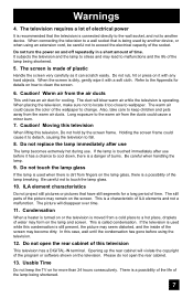
...life of the wallpaper to clean the screen. 6. Also, take care to keep the TV on for a long period of the program or software shown on how to change. ILA element characteristics Do not project still pictures or pictures that have still segments for more than 24 hours consecutively. Usable...of burns. Refer to a wall socket that the television is being shortened. 7 The duct will disappear over time. 11. Please do not open the rear cabinet of ILA elements and not a malfunction. Warnings 4. Do not turn the power on and off repeatedly in a short amount of the picture may ...
...life of the wallpaper to clean the screen. 6. Also, take care to keep the TV on for a long period of the program or software shown on how to change. ILA element characteristics Do not project still pictures or pictures that have still segments for more than 24 hours consecutively. Usable...of burns. Refer to a wall socket that the television is being shortened. 7 The duct will disappear over time. 11. Please do not open the rear cabinet of ILA elements and not a malfunction. Warnings 4. Do not turn the power on and off repeatedly in a short amount of the picture may ...
Instructions
Page 8
... Noise Muting 53 Front Panel Lock 54 V1 Smart Input 54 Video Input Label 55 Position Adjustment 56 Power Indicator 56 Video-1 Monitor Out 57 TV Speaker 57 Audio Out 57 Digital-In 58 Digital-In Audio 58 Center CH Input 59 Picture Adjust 60 Picture Settings 60 Adjust Picture Settings... Function 67 Twin 67 Index 68 Freeze 68 Swap 68 Select 68 Power 69 Number Buttons 69 Tune 69 Input 69 TheaterPro D6500K 69 Return+/TV 70 Sound 70 Muting 71 Video Status 71 Natural Cinema 71 Sleep Timer 72 ML/MTS 72 Display 73 C.C 73 Channel 73 Volume 73 Favorite...
... Noise Muting 53 Front Panel Lock 54 V1 Smart Input 54 Video Input Label 55 Position Adjustment 56 Power Indicator 56 Video-1 Monitor Out 57 TV Speaker 57 Audio Out 57 Digital-In 58 Digital-In Audio 58 Center CH Input 59 Picture Adjust 60 Picture Settings 60 Adjust Picture Settings... Function 67 Twin 67 Index 68 Freeze 68 Swap 68 Select 68 Power 69 Number Buttons 69 Tune 69 Input 69 TheaterPro D6500K 69 Return+/TV 70 Sound 70 Muting 71 Video Status 71 Natural Cinema 71 Sleep Timer 72 ML/MTS 72 Display 73 C.C 73 Channel 73 Volume 73 Favorite...
Instructions
Page 10
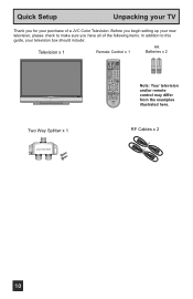
...POWER REC STOP PAUSE OPEN CLOSE STILL PAUSE from the examples RM-C14G illustrated here. Quick Setup Unpacking your TV Thank you have all of the following items. In addition to make sure you for your television box should... include: Television x 1 Remote Control x 1 AA Batteries x 2 AA Alkaline AA Alkaline TV CATV VCR DVD POWER ASPECT MULTI SCREEN TWIN INDEX SELECT SLEEP FREEZE SWAP ML/MTS DISPLAY + INPUT 123 D/A 4 5 6... begin setting up your new television, please check to this guide, your purchase of a JVC Color Television.
...POWER REC STOP PAUSE OPEN CLOSE STILL PAUSE from the examples RM-C14G illustrated here. Quick Setup Unpacking your TV Thank you have all of the following items. In addition to make sure you for your television box should... include: Television x 1 Remote Control x 1 AA Batteries x 2 AA Alkaline AA Alkaline TV CATV VCR DVD POWER ASPECT MULTI SCREEN TWIN INDEX SELECT SLEEP FREEZE SWAP ML/MTS DISPLAY + INPUT 123 D/A 4 5 6... begin setting up your new television, please check to this guide, your purchase of a JVC Color Television.
Instructions
Page 11
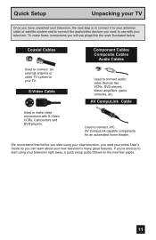
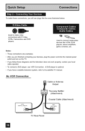
... it to your antenna/ cable or satellite system and to connect the audio/video devices you want to your TV. Coaxial Cables Used to connect an external antenna or cable TV system to use plugs like VCRs, DVD players, stereo amplifiers, game consoles, etc. S-Video Cable Component Cables... Composite Cables Audio Cables Used to connect JVC AV CompuLink capable components for an automated home theater. Used to connect audio/ ...
... it to your antenna/ cable or satellite system and to connect the audio/video devices you want to your TV. Coaxial Cables Used to connect an external antenna or cable TV system to use plugs like VCRs, DVD players, stereo amplifiers, game consoles, etc. S-Video Cable Component Cables... Composite Cables Audio Cables Used to connect JVC AV CompuLink capable components for an automated home theater. Used to connect audio/ ...
Instructions
Page 12
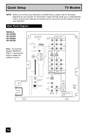
These will help assist you connect your television to another device, as well as use the remote to set up your specific TV and remote. Rear Panel Diagram MODELS: HD-52G886 HD-52G786 HD-56G886 HD-56G786 Note: The terminal labeled "SERVICE ONLY", is exclusively used to update the ...PC IN (D-SUB) L AUDIO OUTPUT 75Ω (VHF/UHF) R R MONITOR /REC OUT LICENSED UNDER THE FOLLOWING U.S. PATENTS 6,183,091 6,419,362 12 Quick Setup TV Models NOTE: Before you in understanding how to connect your television to another device, please refer to the proper diagrams for your television.
These will help assist you connect your television to another device, as well as use the remote to set up your specific TV and remote. Rear Panel Diagram MODELS: HD-52G886 HD-52G786 HD-56G886 HD-56G786 Note: The terminal labeled "SERVICE ONLY", is exclusively used to update the ...PC IN (D-SUB) L AUDIO OUTPUT 75Ω (VHF/UHF) R R MONITOR /REC OUT LICENSED UNDER THE FOLLOWING U.S. PATENTS 6,183,091 6,419,362 12 Quick Setup TV Models NOTE: Before you in understanding how to connect your television to another device, please refer to the proper diagrams for your television.
Instructions
Page 14
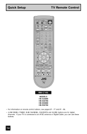
... D/A 4 5 6 i.LINK MENU 78 TIMER TUNE THEATER FAVORITE PRO 0 VIDEO STATUS C.C. NATURAL SOUND CINEMA 9 RETURN+ TV SUB CHANNEL SUB LIGHT MUTING CH GUIDE VOL OK VOL CH MENU VCR CHANNEL PREV NEXT BACK VCR DVD POWER... TV VCR REW PLAY FF REC STOP PAUSE OPEN CLOSE STILL PAUSE RM-C14G RM-C14G MODELS: ...• i.LINK MENU, TIMER, SUB CHANNEL, FAVORITE and GUIDE buttons are for digital channels. If your TV is connected to an ATSC antenna or Digital Cable, you can use these buttons. 14
... D/A 4 5 6 i.LINK MENU 78 TIMER TUNE THEATER FAVORITE PRO 0 VIDEO STATUS C.C. NATURAL SOUND CINEMA 9 RETURN+ TV SUB CHANNEL SUB LIGHT MUTING CH GUIDE VOL OK VOL CH MENU VCR CHANNEL PREV NEXT BACK VCR DVD POWER... TV VCR REW PLAY FF REC STOP PAUSE OPEN CLOSE STILL PAUSE RM-C14G RM-C14G MODELS: ...• i.LINK MENU, TIMER, SUB CHANNEL, FAVORITE and GUIDE buttons are for digital channels. If your TV is connected to an ATSC antenna or Digital Cable, you can use these buttons. 14
Instructions
Page 15
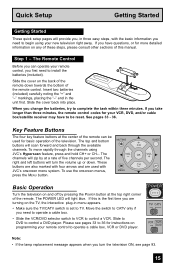
... interactive plug-in menu appears. • Make sure the TV/CATV switch is the first time you have to be used with CH JVC's onscreen menu system. See pages 33 - 36. The channels will zip by pressing the POWER button at a rate of five channels per second. Basic Operation... of the television. To move rapidly through the available CH channels. Move the switch to CATV only if you change the batteries, try to TV. Step 1 - POWER T TV CATV MUL VCR DVD Note: • If the lamp replacement message appears when you need to control a DVD player. The Remote Control Before...
... interactive plug-in menu appears. • Make sure the TV/CATV switch is the first time you have to be used with CH JVC's onscreen menu system. See pages 33 - 36. The channels will zip by pressing the POWER button at a rate of five channels per second. Basic Operation... of the television. To move rapidly through the available CH channels. Move the switch to CATV only if you change the batteries, try to TV. Step 1 - POWER T TV CATV MUL VCR DVD Note: • If the lamp replacement message appears when you need to control a DVD player. The Remote Control Before...
Instructions
Page 16
...Cable or Antenna Output ATSC /DIGITAL CABLE IN I IN Two-way Splitter OUT OUT (Attachment) Coaxial Cable (Attachment) 75Ω (VHF/UHF) TV Rear Panel 16 Used to connect audio/video devices like the ones illustrated below. Notes: • These connections are examples. • After you are ...finished connecting your devices, plug the power cord into the nearest power outlet and turn on the TV. • If you follow these connections, you have a satellite television system, refer to make these diagrams and the television does not work...
...Cable or Antenna Output ATSC /DIGITAL CABLE IN I IN Two-way Splitter OUT OUT (Attachment) Coaxial Cable (Attachment) 75Ω (VHF/UHF) TV Rear Panel 16 Used to connect audio/video devices like the ones illustrated below. Notes: • These connections are examples. • After you are ...finished connecting your devices, plug the power cord into the nearest power outlet and turn on the TV. • If you follow these connections, you have a satellite television system, refer to make these diagrams and the television does not work...
Instructions
Page 17
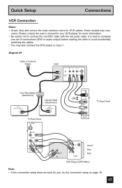
... OUT R L V IN OUT Two-Way Splitter IN (Attachment) OUT OUT Coaxial Cable (Attachment) ATSC /DIGITAL CABLE IN I 75Ω (VHF/UHF) TV Rear Panel S-VIDEO S-VIDEO OR OVER VIDEO L I AUDIO I R INPUT-3 TV Rear Panel OVER Y VIDEO L Pb I AUDIO I R Pr INPUT-1 AUDIO OUT L R Y PB PR OUT Green Blue Red DVD Player (OPTIONAL) Note: • If...
... OUT R L V IN OUT Two-Way Splitter IN (Attachment) OUT OUT Coaxial Cable (Attachment) ATSC /DIGITAL CABLE IN I 75Ω (VHF/UHF) TV Rear Panel S-VIDEO S-VIDEO OR OVER VIDEO L I AUDIO I R INPUT-3 TV Rear Panel OVER Y VIDEO L Pb I AUDIO I R Pr INPUT-1 AUDIO OUT L R Y PB PR OUT Green Blue Red DVD Player (OPTIONAL) Note: • If...
Instructions
Page 18
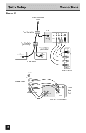
Quick Setup Diagram #2 Cable or Antenna Output Connections Two-Way Splitter IN OUT OUT VCR IN OUT Two-Way Splitter IN (Attachment) OUT OUT Coaxial Cable (Attachment) ATSC /DIGITAL CABLE IN I 75Ω (VHF/UHF) TV Rear Panel S-VIDEO R L V IN OUT S-VIDEO OR OVER VIDEO L I AUDIO I R INPUT-3 TV Rear Panel TV Rear Panel OVER Y VIDEO L Pb I AUDIO I R Pr INPUT-1 AUDIO OUT L R Y PB PR OUT Green Blue Red DVD Player (OPTIONAL) 18
Quick Setup Diagram #2 Cable or Antenna Output Connections Two-Way Splitter IN OUT OUT VCR IN OUT Two-Way Splitter IN (Attachment) OUT OUT Coaxial Cable (Attachment) ATSC /DIGITAL CABLE IN I 75Ω (VHF/UHF) TV Rear Panel S-VIDEO R L V IN OUT S-VIDEO OR OVER VIDEO L I AUDIO I R INPUT-3 TV Rear Panel TV Rear Panel OVER Y VIDEO L Pb I AUDIO I R Pr INPUT-1 AUDIO OUT L R Y PB PR OUT Green Blue Red DVD Player (OPTIONAL) 18
Instructions
Page 19
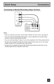
... Cable signal, it can be outputted to the S-Video output terminal or Video (composite video) terminal. • If you are receiving Analog TV signal, it can not be outputted to ON. Quick Setup Connections Connecting to Monitor/Recording Output Terminal S-VIDEO VIDEO L AUDIO R MONITOR /REC OUT... TV Rear Panel VCR IN OUT OR R L V IN OUT Notes: • When you are not viewing images coming from the composite video input terminal. •...
... Cable signal, it can be outputted to the S-Video output terminal or Video (composite video) terminal. • If you are receiving Analog TV signal, it can not be outputted to ON. Quick Setup Connections Connecting to Monitor/Recording Output Terminal S-VIDEO VIDEO L AUDIO R MONITOR /REC OUT... TV Rear Panel VCR IN OUT OR R L V IN OUT Notes: • When you are not viewing images coming from the composite video input terminal. •...
Instructions
Page 20
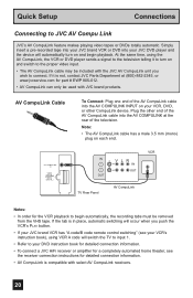
... player sends a signal to the television telling it is not, contact JVC Parts Department at the rear of the television. Plug the other CompuLink device. AV COMPULINK III VIDEO (DIGITAL) _ AUDIO (DIGITAL) IN V L R IN OUT OUT TV Rear Panel AV CompuLink VCR Notes: • In order for part # ...EWP 805-012. • AV CompuLink can only be used with the JVC AV CompuLink unit you push the VCR's PLAY button. • If your...
... player sends a signal to the television telling it is not, contact JVC Parts Department at the rear of the television. Plug the other CompuLink device. AV COMPULINK III VIDEO (DIGITAL) _ AUDIO (DIGITAL) IN V L R IN OUT OUT TV Rear Panel AV CompuLink VCR Notes: • In order for part # ...EWP 805-012. • AV CompuLink can only be used with the JVC AV CompuLink unit you push the VCR's PLAY button. • If your...
Instructions
Page 21
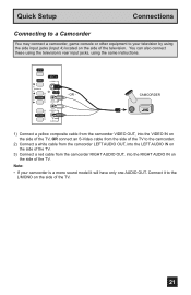
...sound model it to the camcorder. 2) Connect a white cable from the camcorder LEFT AUDIO OUT, into the LEFT AUDIO IN on the side of the TV. 3) Connect a red cable from the camcorder RIGHT AUDIO OUT, into the RIGHT AUDIO IN on the side of the television. You can also connect these... using the television's rear input jacks, using the side input jacks (Input 4) located on the side of the TV. OVER VIDEO + VOLUME - Note: • If your television by using the same instructions.
...sound model it to the camcorder. 2) Connect a white cable from the camcorder LEFT AUDIO OUT, into the LEFT AUDIO IN on the side of the TV. 3) Connect a red cable from the camcorder RIGHT AUDIO OUT, into the RIGHT AUDIO IN on the side of the television. You can also connect these... using the television's rear input jacks, using the side input jacks (Input 4) located on the side of the TV. OVER VIDEO + VOLUME - Note: • If your television by using the same instructions.
Instructions
Page 22
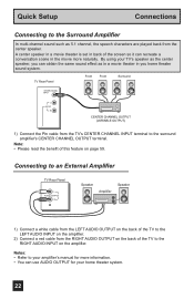
... the RIGHT AUDIO INPUT on page 59. Connecting to an External Amplifier TV Rear Panel L AUDIO OUTPUT R Speaker Amplifier Speaker 1) Connect a white cable from the LEFT AUDIO OUTPUT on the back of the TV to the LEFT AUDIO INPUT on the amplifier. 2) Connect a red cable from the ... on the back of this feature on the amplifier. Notes: • Refer to your amplifier's manual for your TV's speaker as the center speaker, you home theater sound system. TV Rear Panel Front Front Surround CENTER CHANNEL INPUT L AUDIO R CENTER CHANNEL OUTPUT (VARIABLE OUTPUT) 1) Connect the Pin cable...
... the RIGHT AUDIO INPUT on page 59. Connecting to an External Amplifier TV Rear Panel L AUDIO OUTPUT R Speaker Amplifier Speaker 1) Connect a white cable from the LEFT AUDIO OUTPUT on the back of the TV to the LEFT AUDIO INPUT on the amplifier. 2) Connect a red cable from the ... on the back of this feature on the amplifier. Notes: • Refer to your amplifier's manual for your TV's speaker as the center speaker, you home theater sound system. TV Rear Panel Front Front Surround CENTER CHANNEL INPUT L AUDIO R CENTER CHANNEL OUTPUT (VARIABLE OUTPUT) 1) Connect the Pin cable...
Instructions
Page 23
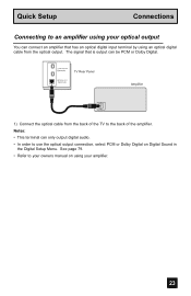
... or Dolby Digital on using your amplifier. 23 Quick Setup Connections Connecting to the back of the TV to an amplifier using your optical output You can be PCM or Dolby Digital. i.LINK IN/OUT S400(TS) TV Rear Panel OPTICAL OUT Digital Audio Amplifier 1) Connect the optical cable from the optical output.
... or Dolby Digital on using your amplifier. 23 Quick Setup Connections Connecting to the back of the TV to an amplifier using your optical output You can be PCM or Dolby Digital. i.LINK IN/OUT S400(TS) TV Rear Panel OPTICAL OUT Digital Audio Amplifier 1) Connect the optical cable from the optical output.
Instructions
Page 24
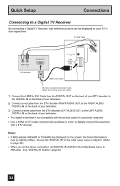
... 720x480) are displayed on the back of your television. • The digital-in terminal is not compatible with the picture signal of your TV in order to digitally connect the television with a DTV decoder. See "DIGITAL-IN AUDIO", page 58. 24 Access the "DIGITAL-IN" ...the above connection, set DIGITAL-IN AUDIO in the Initial Setup menu to a Digital TV Receiver By connecting a Digital TV Receiver, high definition pictures can be slightly shifted. Quick Setup Connections Connecting to ANALOG. TV Rear Panel AUDIO OUT LR DTV Decoder DIGITAL OUT AV COMPULINK III VIDEO (DIGITAL) _ ...
... 720x480) are displayed on the back of your television. • The digital-in terminal is not compatible with the picture signal of your TV in order to digitally connect the television with a DTV decoder. See "DIGITAL-IN AUDIO", page 58. 24 Access the "DIGITAL-IN" ...the above connection, set DIGITAL-IN AUDIO in the Initial Setup menu to a Digital TV Receiver By connecting a Digital TV Receiver, high definition pictures can be slightly shifted. Quick Setup Connections Connecting to ANALOG. TV Rear Panel AUDIO OUT LR DTV Decoder DIGITAL OUT AV COMPULINK III VIDEO (DIGITAL) _ ...


