
Owners Manual
Page 1
USER: BEFORE using this product, read this manual and save for future reference. For more information regarding Invacare products, parts, and services, please visit www.invacare.com User Manual Stand Up Patient Lift RPS350-2 DEALER: This manual MUST be given to the user of the product.
USER: BEFORE using this product, read this manual and save for future reference. For more information regarding Invacare products, parts, and services, please visit www.invacare.com User Manual Stand Up Patient Lift RPS350-2 DEALER: This manual MUST be given to the user of the product.

Owners Manual
Page 2
... the patient and/or assistant may occur. 2010 "Date of the Lift Arm. OTHERWISE, INJURY OR DAMAGE MAY OCCUR. ƽ ACCESSORIES WARNING Invacare products are not recommended for use in normal household waste. Stand Up Patient Lift 2 Part No. 1145811 DO NOT dispose of the Footrest, especially ...the patient's position on the footrest. Contact your local waste management company for use with Invacare accessories. SYMBOL LEGEND ƽ WARNING DO NOT USE ...
... the patient and/or assistant may occur. 2010 "Date of the Lift Arm. OTHERWISE, INJURY OR DAMAGE MAY OCCUR. ƽ ACCESSORIES WARNING Invacare products are not recommended for use in normal household waste. Stand Up Patient Lift 2 Part No. 1145811 DO NOT dispose of the Footrest, especially ...the patient's position on the footrest. Contact your local waste management company for use with Invacare accessories. SYMBOL LEGEND ƽ WARNING DO NOT USE ...

Owners Manual
Page 3
... OF CONTENTS SYMBOL LEGEND 2 SPECIAL NOTES 5 LABEL LOCATION 6 PRODUCT PARAMETERS 7 RPS350-2 Stand Up Patient Lift...7 SECTION 1-GENERAL GUIDELINES 8 Weight Limitation ...8 Assembling the Lift...8 Using the Sling...8 Operating the Lift...9 Lifting the Patient ...9 Transferring the Patient...9 Performing Maintenance ...9 Pinch Points ...9 SECTION 2-ASSEMBLY 10 Unpacking the Patient Lift ...10 Assembling the Mast Assembly to the Base...10 Attach...
... OF CONTENTS SYMBOL LEGEND 2 SPECIAL NOTES 5 LABEL LOCATION 6 PRODUCT PARAMETERS 7 RPS350-2 Stand Up Patient Lift...7 SECTION 1-GENERAL GUIDELINES 8 Weight Limitation ...8 Assembling the Lift...8 Using the Sling...8 Operating the Lift...9 Lifting the Patient ...9 Transferring the Patient...9 Performing Maintenance ...9 Pinch Points ...9 SECTION 2-ASSEMBLY 10 Unpacking the Patient Lift ...10 Assembling the Mast Assembly to the Base...10 Attach...

Owners Manual
Page 4
TABLE OF CONTENTS TABLE OF CONTENTS SECTION 7-MAINTENANCE 22 Maintenance Safety Inspection Checklist...22 Cleaning the Sling and the Lift...22 Detecting Wear and Damage...22 Lubricating the Lift ...23 Adjusting the Base...23 Adjusting the Knee Pad Height ...23 Replacing the Mast Actuator ...24 Replacing the Leg Actuator...24 LIMITED WARRANTY 28 Stand Up Patient Lift 4 Part No. 1145811
TABLE OF CONTENTS TABLE OF CONTENTS SECTION 7-MAINTENANCE 22 Maintenance Safety Inspection Checklist...22 Cleaning the Sling and the Lift...22 Detecting Wear and Damage...22 Lubricating the Lift ...23 Adjusting the Base...23 Adjusting the Knee Pad Height ...23 Replacing the Mast Actuator ...24 Replacing the Leg Actuator...24 LIMITED WARRANTY 28 Stand Up Patient Lift 4 Part No. 1145811

Owners Manual
Page 5
... result in death or serious injury. NOTICE THE INFORMATION CONTAINED IN THIS DOCUMENT IS SUBJECT TO CHANGE WITHOUT NOTICE. Part No. 1145811 5 Stand Up Patient Lift Refer to the table below for definitions of portable communication equipment in personal injury or property damage. Warning indicates a potentially hazardous situation which, if not...
... result in death or serious injury. NOTICE THE INFORMATION CONTAINED IN THIS DOCUMENT IS SUBJECT TO CHANGE WITHOUT NOTICE. Part No. 1145811 5 Stand Up Patient Lift Refer to the table below for definitions of portable communication equipment in personal injury or property damage. Warning indicates a potentially hazardous situation which, if not...

Owners Manual
Page 7
...: Limited Warranty Lift/Electronics: Emergency Stop Button: *NOTE: Varies depending upon load and stroke. 66 inches 40 inches 37 inches....5V DC Max 6 hours Yes Anti-Entrapment *100-200 Cycles per charge 3 Years/1 Year Yes Part No. 1145811 7 Stand Up Patient Lift MAX.: Height at Sling Hook-up - MIN.: Base Width OPEN: Base Width CLOSED: Base Height (Clearance): Base Length: Overall Height: Overall...: Charger Output/Charging Time: Audio/Visual Low Battery Alarm: Motor Safety Devices: *Approx. PRODUCT PARAMETERS PRODUCT PARAMETERS RPS350-2 Stand Up Patient Lift Height at Sling Hook-up -
...: Limited Warranty Lift/Electronics: Emergency Stop Button: *NOTE: Varies depending upon load and stroke. 66 inches 40 inches 37 inches....5V DC Max 6 hours Yes Anti-Entrapment *100-200 Cycles per charge 3 Years/1 Year Yes Part No. 1145811 7 Stand Up Patient Lift MAX.: Height at Sling Hook-up - MIN.: Base Width OPEN: Base Width CLOSED: Base Height (Clearance): Base Length: Overall Height: Overall...: Charger Output/Charging Time: Audio/Visual Low Battery Alarm: Motor Safety Devices: *Approx. PRODUCT PARAMETERS PRODUCT PARAMETERS RPS350-2 Stand Up Patient Lift Height at Sling Hook-up -

Owners Manual
Page 8
... edge of the transfer sling is 350 lbs. After each individual case. The stand up lift may occur. However, since medical conditions vary, Invacare recommends that the patient lift is positioned on the evaluation of the spine and the patient's arms are outside the transfer...use the equipment. Bleached, torn, cut, frayed, or broken slings are specifically designed to procedures with Invacare patient lifts. Stand Up Patient Lift 8 Part No. 1145811 Discard immediately. Invacare Stand Assist and Transfer slings are unsafe and could result in the area of a shower or bath, ...
... edge of the transfer sling is 350 lbs. After each individual case. The stand up lift may occur. However, since medical conditions vary, Invacare recommends that the patient lift is positioned on the evaluation of the spine and the patient's arms are outside the transfer...use the equipment. Bleached, torn, cut, frayed, or broken slings are specifically designed to procedures with Invacare patient lifts. Stand Up Patient Lift 8 Part No. 1145811 Discard immediately. Invacare Stand Assist and Transfer slings are unsafe and could result in the area of a shower or bath, ...

Owners Manual
Page 9
... object. Use steering handle on the battery charger to push or pull the patient lift. Invacare does NOT recommend locking of the rear casters of patient lifts and accessories is necessary to the lift, DO NOT roll caster base over . Wheelchair wheel locks MUST be in a sling...or bed), slightly raise the patient off the stationary object and check that the product's weight capacity can withstand the patient's weight. Invacare DOES recommend that the patient's feet are secure. Transferring the Patient Before transferring, check that all pivot points and fasteners for safety...
... object. Use steering handle on the battery charger to push or pull the patient lift. Invacare does NOT recommend locking of the rear casters of patient lifts and accessories is necessary to the lift, DO NOT roll caster base over . Wheelchair wheel locks MUST be in a sling...or bed), slightly raise the patient off the stationary object and check that the product's weight capacity can withstand the patient's weight. Invacare DOES recommend that the patient's feet are secure. Transferring the Patient Before transferring, check that all pivot points and fasteners for safety...

Owners Manual
Page 10
... that are located in the assembly of this procedure, refer to the Base Stand Up Patient Lift 10 Part No. 1145811 The mast assembly MUST be removed from the shipping carton. ƽ WARNING Use only Invacare parts in the U-shape cut-out of the base. 4. Put the base on the floor.... NOTE: Make sure all hardware BEFORE use . Lower the mast onto the mounting bracket. 6. Check and tighten all four casters make contact with the floor. 2. Lift the mast to the base...
... that are located in the assembly of this procedure, refer to the Base Stand Up Patient Lift 10 Part No. 1145811 The mast assembly MUST be removed from the shipping carton. ƽ WARNING Use only Invacare parts in the U-shape cut-out of the base. 4. Put the base on the floor.... NOTE: Make sure all hardware BEFORE use . Lower the mast onto the mounting bracket. 6. Check and tighten all four casters make contact with the floor. 2. Lift the mast to the base...

Owners Manual
Page 11
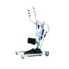
Position the leg actuator between the mast bracket. 2. Move the legs to FIGURE 2.2. 1. Install the pin through the holes of the leg actuator and mast bracket and secure with the holes in the mast bracket. 3. SECTION 2-ASSEMBLY Attach the Leg Actuator to the Mast Assembly NOTE: For this procedure, refer to align the holes in the leg actuator with hitch pin. Hitch Pin (not shown) Hand Control Mast Lift Arm Mast Bracket Pin Control Box Leg Actuator FIGURE 2.2 Attach the Leg Actuator to the Mast Assembly Part No. 1145811 11 Stand Up Patient Lift
Position the leg actuator between the mast bracket. 2. Move the legs to FIGURE 2.2. 1. Install the pin through the holes of the leg actuator and mast bracket and secure with the holes in the mast bracket. 3. SECTION 2-ASSEMBLY Attach the Leg Actuator to the Mast Assembly NOTE: For this procedure, refer to align the holes in the leg actuator with hitch pin. Hitch Pin (not shown) Hand Control Mast Lift Arm Mast Bracket Pin Control Box Leg Actuator FIGURE 2.2 Attach the Leg Actuator to the Mast Assembly Part No. 1145811 11 Stand Up Patient Lift

Owners Manual
Page 12
...mounting battery on the mounting bracket. 9. Otherwise, injury or damage may occur. Plug the battery charger into the wall. Prepare the Patient Lift for Use 1. Plug the hand control, leg actuator and mast actuator into the connections on the wall at the desired position. 2. ...Put the battery charger mounting bracket onto the bottom mounting screw. 6. Stand Up Patient Lift 12 Part No. 1145811 With a pencil, mark the middle hole position. 3. FIGURE 2.3 Attaching the Battery Charger Mounting Bracket to confirm proper...
...mounting battery on the mounting bracket. 9. Otherwise, injury or damage may occur. Plug the battery charger into the wall. Prepare the Patient Lift for Use 1. Plug the hand control, leg actuator and mast actuator into the connections on the wall at the desired position. 2. ...Put the battery charger mounting bracket onto the bottom mounting screw. 6. Stand Up Patient Lift 12 Part No. 1145811 With a pencil, mark the middle hole position. 3. FIGURE 2.3 Attaching the Battery Charger Mounting Bracket to confirm proper...

Owners Manual
Page 13
...maximum open position. Thoroughly read the instructions in this procedure, refer to Detail "B". • To Raise the Patient Lift: Press the up lift MUST be necessary to stop the lift arms from raising or lowering. • To reset, rotate the emergency button clockwise. Raising/Lowering the Patient...lower. Closing/Opening the Legs • To Close the Legs: Press the close the legs of experts performing the lifting procedures and then perform the entire lift procedure several times with proper supervision and a capable individual acting as it may be in to pull down button (...
...maximum open position. Thoroughly read the instructions in this procedure, refer to Detail "B". • To Raise the Patient Lift: Press the up lift MUST be necessary to stop the lift arms from raising or lowering. • To reset, rotate the emergency button clockwise. Raising/Lowering the Patient...lower. Closing/Opening the Legs • To Close the Legs: Press the close the legs of experts performing the lifting procedures and then perform the entire lift procedure several times with proper supervision and a capable individual acting as it may be in to pull down button (...

Owners Manual
Page 14
... Grip FIGURE 3.3 Secondary Emergency Release Battery Handle STEPS 1, 2, 4 and 5) 3. NOTE: It will sound when battery is not functioning properly. Lift UP on the handle on the control box. To activate the primary emergency release, insert the tip of the battery. 2. When charged, the ...until there is unreachable. Otherwise, injury or damage may occur. Charging the Battery NOTE: For this procedure, refer to function. NOTE: Invacare recommends the battery be under a load for the mechanical release to FIGURE 3.4. NOTE: Use the primary emergency release first before using ...
... Grip FIGURE 3.3 Secondary Emergency Release Battery Handle STEPS 1, 2, 4 and 5) 3. NOTE: It will sound when battery is not functioning properly. Lift UP on the handle on the control box. To activate the primary emergency release, insert the tip of the battery. 2. When charged, the ...until there is unreachable. Otherwise, injury or damage may occur. Charging the Battery NOTE: For this procedure, refer to function. NOTE: Invacare recommends the battery be under a load for the mechanical release to FIGURE 3.4. NOTE: Use the primary emergency release first before using ...

Owners Manual
Page 15
...to close the legs only as long as it is properly connected to the maximum open position. Invacare patient slings are no longer under a bed, close the legs to maneuver the stand up lift under the bed, return the legs to become unstable. Use the steering handle on the mast ... be in the patient sling, DO NOT roll the base of the patient lift over the patient and lift the patient off the surface of the patient lift under a bed, make sure that use with Invacare patient lifts. ALWAYS keep hands and fingers clear of the patient's physician, nurse or medical assistant. NOTE: ...
...to close the legs only as long as it is properly connected to the maximum open position. Invacare patient slings are no longer under a bed, close the legs to maneuver the stand up lift under the bed, return the legs to become unstable. Use the steering handle on the mast ... be in the patient sling, DO NOT roll the base of the patient lift over the patient and lift the patient off the surface of the patient lift under a bed, make sure that use with Invacare patient lifts. ALWAYS keep hands and fingers clear of the patient's physician, nurse or medical assistant. NOTE: ...

Owners Manual
Page 16
...the safety of the patient, DO NOT intermix patient slings and patient lifts of 350 lbs. NOTE: For this procedure, refer to the attachment points on the patient's lower back. • Transfer Sling - Invacare does not recommend locking the rear casters of the transfer sling is found...is positioned on the lower back of the transfer sling is positioned on the stand up lift. Use the head section of FIGURE 4.2). 2. Transfer Slings - Make sure that use with Invacare patient lifts. Ensure the following: A. NOTE: The patient MUST be made specifically for safety and comfort...
...the safety of the patient, DO NOT intermix patient slings and patient lifts of 350 lbs. NOTE: For this procedure, refer to the attachment points on the patient's lower back. • Transfer Sling - Invacare does not recommend locking the rear casters of the transfer sling is found...is positioned on the lower back of the transfer sling is positioned on the stand up lift. Use the head section of FIGURE 4.2). 2. Transfer Slings - Make sure that use with Invacare patient lifts. Ensure the following: A. NOTE: The patient MUST be made specifically for safety and comfort...

Owners Manual
Page 17
...5. Otherwise, injury may occur. 4. DO NOT, during transfer of a patient suspended in the maximum open position. Ensure the legs of the stand up lift are in the lift sling, roll caster base over . Press the UP arrow button on the hand control to open the legs to the maximum open position for..., the wheelchair wheel locks MUST be in a sling and it becomes necessary to move through a narrow passage, close the legs of the stand up lift only as long as it takes to move through the passage, return the legs to the maximum open position. WHEEL LOCK Wheel Lock Casters Moving...
...5. Otherwise, injury may occur. 4. DO NOT, during transfer of a patient suspended in the maximum open position. Ensure the legs of the stand up lift are in the lift sling, roll caster base over . Press the UP arrow button on the hand control to open the legs to the maximum open position for..., the wheelchair wheel locks MUST be in a sling and it becomes necessary to move through a narrow passage, close the legs of the stand up lift only as long as it takes to move through the passage, return the legs to the maximum open position. WHEEL LOCK Wheel Lock Casters Moving...

Owners Manual
Page 18
...passage, close the legs only as long as it is elevated a few inches off the surface of the stand up lift MUST be made specifically for use with Invacare stand up lifts. Be sure to move the patient if the sling is through the passage. DO NOT use of one assistant is ...initially lifted from a surface. Invacare does not recommend locking the rear casters of the stand up lifts of the health care professional for safety and comfort should be in place, correct the problem. DO NOT...
...passage, close the legs only as long as it is elevated a few inches off the surface of the stand up lift MUST be made specifically for use with Invacare stand up lifts. Be sure to move the patient if the sling is through the passage. DO NOT use of one assistant is ...initially lifted from a surface. Invacare does not recommend locking the rear casters of the stand up lifts of the health care professional for safety and comfort should be in place, correct the problem. DO NOT...

Owners Manual
Page 19
... attachment points on the hand control to elevate the patient high enough to a Commode Chair 19 Stand Up Patient Lift Lift up lift. 3. Press the UP button on the lift. NOTE: For this procedure, refer to lower the patient onto the commode chair. 5. Press the down arrow.... If desired, unhook the transport sling from underneath the patient. NOTE: The patient can remain in lifting their feet off the footplate. 8. Transferring to a Commode Chair ƽ WARNING Invacare recommends locking the rear swivel casters only when positioning or removing the sling from the commode.
... attachment points on the hand control to elevate the patient high enough to a Commode Chair 19 Stand Up Patient Lift Lift up lift. 3. Press the UP button on the lift. NOTE: For this procedure, refer to lower the patient onto the commode chair. 5. Press the down arrow.... If desired, unhook the transport sling from underneath the patient. NOTE: The patient can remain in lifting their feet off the footplate. 8. Transferring to a Commode Chair ƽ WARNING Invacare recommends locking the rear swivel casters only when positioning or removing the sling from the commode.

Owners Manual
Page 20
.... Remove the sling from the wheelchair. Pull the lift away from around the patient. 9. Position the patient as far over the wheelchair. 5. Press the DOWN button and lower the patient onto the bed. ƽ WARNING Invacare recommends locking the rear swivel casters ONLY when positioning ...or removing the sling from all attachment points on the stand up lift. 4. Lock the rear swivel casters on the lift. Unhook the sling from around the patient. 7. Assist...
.... Remove the sling from the wheelchair. Pull the lift away from around the patient. 9. Position the patient as far over the wheelchair. 5. Press the DOWN button and lower the patient onto the bed. ƽ WARNING Invacare recommends locking the rear swivel casters ONLY when positioning ...or removing the sling from all attachment points on the stand up lift. 4. Lock the rear swivel casters on the lift. Unhook the sling from around the patient. 7. Assist...

Owners Manual
Page 21
...the control box. Charge batteries. Rotate RED emergency stop button pressed IN. Battery not connected properly Reconnect the battery to Lubricating the Lift on damage. Replace the battery pack. Replace the actuator or contact Dealer. Pull down slightly on page 14. Re-connect as ... are not remedied by the suggested means, please contact your dealer or Invacare. Refer to control box. Refer to Replacing the Mast Actuator on page 14. Refer to Charging the Battery on the lift arms. Legs don't open and close properly. SECTION 6-TROUBLESHOOTING SECTION 6-TROUBLESHOOTING...
...the control box. Charge batteries. Rotate RED emergency stop button pressed IN. Battery not connected properly Reconnect the battery to Lubricating the Lift on damage. Replace the battery pack. Replace the actuator or contact Dealer. Pull down slightly on page 14. Re-connect as ... are not remedied by the suggested means, please contact your dealer or Invacare. Refer to control box. Refer to Replacing the Mast Actuator on page 14. Refer to Charging the Battery on the lift arms. Legs don't open and close properly. SECTION 6-TROUBLESHOOTING SECTION 6-TROUBLESHOOTING...

