
Owners Manual
Page 3
TABLE OF CONTENTS TABLE OF CONTENTS SYMBOL LEGEND 2 SPECIAL NOTES 5 LABEL LOCATION 6 PRODUCT PARAMETERS 7 RPS350-2 Stand Up Patient Lift...7 SECTION 1-GENERAL GUIDELINES 8 Weight Limitation ...8 Assembling the Lift...8 Using the Sling...8 Operating the Lift...9 Lifting the ... Maintenance ...9 Pinch Points ...9 SECTION 2-ASSEMBLY 10 Unpacking the Patient Lift ...10 Assembling the Mast Assembly to the Base...10 Attach the Leg Actuator to the Mast Assembly ...11 Attaching the Battery Charger Mounting Bracket to a Bed ...20 SECTION 6-TROUBLESHOOTING 21 Part No. 1145811 3 Stand Up...
TABLE OF CONTENTS TABLE OF CONTENTS SYMBOL LEGEND 2 SPECIAL NOTES 5 LABEL LOCATION 6 PRODUCT PARAMETERS 7 RPS350-2 Stand Up Patient Lift...7 SECTION 1-GENERAL GUIDELINES 8 Weight Limitation ...8 Assembling the Lift...8 Using the Sling...8 Operating the Lift...9 Lifting the ... Maintenance ...9 Pinch Points ...9 SECTION 2-ASSEMBLY 10 Unpacking the Patient Lift ...10 Assembling the Mast Assembly to the Base...10 Attach the Leg Actuator to the Mast Assembly ...11 Attaching the Battery Charger Mounting Bracket to a Bed ...20 SECTION 6-TROUBLESHOOTING 21 Part No. 1145811 3 Stand Up...

Owners Manual
Page 4
TABLE OF CONTENTS TABLE OF CONTENTS SECTION 7-MAINTENANCE 22 Maintenance Safety Inspection Checklist...22 Cleaning the Sling and the Lift...22 Detecting Wear and Damage...22 Lubricating the Lift ...23 Adjusting the Base...23 Adjusting the Knee Pad Height ...23 Replacing the Mast Actuator ...24 Replacing the Leg Actuator...24 LIMITED WARRANTY 28 Stand Up Patient Lift 4 Part No. 1145811
TABLE OF CONTENTS TABLE OF CONTENTS SECTION 7-MAINTENANCE 22 Maintenance Safety Inspection Checklist...22 Cleaning the Sling and the Lift...22 Detecting Wear and Damage...22 Lubricating the Lift ...23 Adjusting the Base...23 Adjusting the Knee Pad Height ...23 Replacing the Mast Actuator ...24 Replacing the Leg Actuator...24 LIMITED WARRANTY 28 Stand Up Patient Lift 4 Part No. 1145811

Owners Manual
Page 11
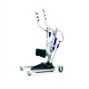
Position the leg actuator between the mast bracket. 2. SECTION 2-ASSEMBLY Attach the Leg Actuator to the Mast Assembly NOTE: For this procedure, refer to align the holes in the mast bracket. 3. Move the legs to FIGURE 2.2. 1. Hitch Pin (not shown) Hand Control Mast Lift Arm Mast Bracket Pin Control Box Leg Actuator FIGURE 2.2 Attach the Leg Actuator to the Mast Assembly Part No. 1145811 11 Stand Up Patient Lift Install the pin through the holes of the leg actuator and mast bracket and secure with the holes in the leg actuator with hitch pin.
Position the leg actuator between the mast bracket. 2. SECTION 2-ASSEMBLY Attach the Leg Actuator to the Mast Assembly NOTE: For this procedure, refer to align the holes in the mast bracket. 3. Move the legs to FIGURE 2.2. 1. Hitch Pin (not shown) Hand Control Mast Lift Arm Mast Bracket Pin Control Box Leg Actuator FIGURE 2.2 Attach the Leg Actuator to the Mast Assembly Part No. 1145811 11 Stand Up Patient Lift Install the pin through the holes of the leg actuator and mast bracket and secure with the holes in the leg actuator with hitch pin.

Owners Manual
Page 12
... procedure, refer to the Wall 8. Plug the battery charger into the connections on the wall at the desired position. 2. Plug the hand control, leg actuator and mast actuator into an electrical outlet. Measure down 6½ inches from the pencil mark and drill one mounting hole. 4. Put the battery charger mounting bracket onto...
... procedure, refer to the Wall 8. Plug the battery charger into the connections on the wall at the desired position. 2. Plug the hand control, leg actuator and mast actuator into an electrical outlet. Measure down 6½ inches from the pencil mark and drill one mounting hole. 4. Put the battery charger mounting bracket onto...

Owners Manual
Page 14
...No. 1145811 When charged, the LED will take approximately four hours to charge a battery that requires a full charge. 4. NOTE: All patient lift actuators are equipped with a mechanical emergency release. NOTE: The lift MUST be recharged daily to function. To activate the secondary emergency release, pull up ...the RED emergency grip and pull down if the hand control is an audible click when mounting battery on the battery charger. NOTE: Invacare recommends the battery be under a load for the mechanical release to prolong battery life. Place the battery on the boom at the ...
...No. 1145811 When charged, the LED will take approximately four hours to charge a battery that requires a full charge. 4. NOTE: All patient lift actuators are equipped with a mechanical emergency release. NOTE: The lift MUST be recharged daily to function. To activate the secondary emergency release, pull up ...the RED emergency grip and pull down if the hand control is an audible click when mounting battery on the battery charger. NOTE: Invacare recommends the battery be under a load for the mechanical release to prolong battery life. Place the battery on the boom at the ...

Owners Manual
Page 21
...emergency stop button pressed IN. Refer to Replacing the Mast Actuator on page 14. Re-connect as necessary. The connecting terminals are not remedied by the suggested means, please contact your dealer or Invacare. Replace the battery pack. Refer to Charging the Battery... to Adjusting the Base on page 14. Check the hand control and actuator connections. page 24. SECTION 6-TROUBLESHOOTING SECTION 6-TROUBLESHOOTING SYMPTOMS Noisy or dry sound from actuator. Hand-control or actuator connector loose. RED emergency stop button CLOCKWISE until it pops out. Lift...
...emergency stop button pressed IN. Refer to Replacing the Mast Actuator on page 14. Re-connect as necessary. The connecting terminals are not remedied by the suggested means, please contact your dealer or Invacare. Replace the battery pack. Refer to Charging the Battery... to Adjusting the Base on page 14. Check the hand control and actuator connections. page 24. SECTION 6-TROUBLESHOOTING SECTION 6-TROUBLESHOOTING SYMPTOMS Noisy or dry sound from actuator. Hand-control or actuator connector loose. RED emergency stop button CLOCKWISE until it pops out. Lift...

Owners Manual
Page 22
...that the lift is important to ensure smooth quiet operation. X X X Inspect to metal contact will wear after considerable use. X X X ELECTRIC ACTUATORS Check for wear. X X X CLEANING Whenever necessary. Remove all hardware and attachment points. Replace any parts are centered between the base legs. X... with minimum care and maintenance. X X X SLINGS CHECK ALL SLING ATTACHMENTS each time it is no adjustment or maintenance of the Invacare Lift are made . There is used until repairs are clear of any pivot for slings for wear. X X X THE LIFT ...
...that the lift is important to ensure smooth quiet operation. X X X Inspect to metal contact will wear after considerable use. X X X ELECTRIC ACTUATORS Check for wear. X X X CLEANING Whenever necessary. Remove all hardware and attachment points. Replace any parts are centered between the base legs. X... with minimum care and maintenance. X X X SLINGS CHECK ALL SLING ATTACHMENTS each time it is no adjustment or maintenance of the Invacare Lift are made . There is used until repairs are clear of any pivot for slings for wear. X X X THE LIFT ...

Owners Manual
Page 24
.... 2. A. C. Stand Up Patient Lift 24 Part No. 1145811 Otherwise, injury to personnel or damage to install the new electric actuator. ƽ WARNING DO NOT overtighten mounting hardware. Reverse STEPS 1-3 to the patient lift may occur. Bracket Bolt Washer Bushing Bolt Washer... Nut Washer Bushing Bolt Washer Replacing the Leg Actuator FIGURE 7.3 Replacing the Mast Actuator NOTE: For this procedure, refer to FIGURE 7.3. 1. This will damage mounting brackets. Return the lift to the upright ...
.... 2. A. C. Stand Up Patient Lift 24 Part No. 1145811 Otherwise, injury to personnel or damage to install the new electric actuator. ƽ WARNING DO NOT overtighten mounting hardware. Reverse STEPS 1-3 to the patient lift may occur. Bracket Bolt Washer Bushing Bolt Washer... Nut Washer Bushing Bolt Washer Replacing the Leg Actuator FIGURE 7.3 Replacing the Mast Actuator NOTE: For this procedure, refer to FIGURE 7.3. 1. This will damage mounting brackets. Return the lift to the upright ...

Owners Manual
Page 25
...the control box. Leg Base Pivot Bracket Hitch Pin Hand Control Leg Actuator Pin Lift Arm Hitch Pin (not shown) Mast Bracket Pin Part No. 1145811 Mast Battery and Control Box Mast Actuator Leg Actuator Slot in the leg actuator with hitch pin. 5. Plug the hand control into the bottom ...of the leg actuator and mast bracket and secure with the holes in the mast bracket. C. Position the ...
...the control box. Leg Base Pivot Bracket Hitch Pin Hand Control Leg Actuator Pin Lift Arm Hitch Pin (not shown) Mast Bracket Pin Part No. 1145811 Mast Battery and Control Box Mast Actuator Leg Actuator Slot in the leg actuator with hitch pin. 5. Plug the hand control into the bottom ...of the leg actuator and mast bracket and secure with the holes in the mast bracket. C. Position the ...