
Owners Manual
Page 1
For more information regarding Invacare products, parts, and services, please visit www.invacare.com USER: BEFORE using this product, read this manual and save for future reference. User Manual Stand Up Patient Lift RPS350-2 DEALER: This manual MUST be given to the user of the product.
For more information regarding Invacare products, parts, and services, please visit www.invacare.com USER: BEFORE using this product, read this manual and save for future reference. User Manual Stand Up Patient Lift RPS350-2 DEALER: This manual MUST be given to the user of the product.

Owners Manual
Page 2
...site. Accessories designed by other manufacturers have not been tested by Invacare and are specifically designed and manufactured for use with Invacare accessories. ALWAYS be aware of the Footrest, especially the patient's position on the footrest. ALWAYS be taken to the patient and/or assistant may occur. 2010 "Date of batteries in ...WARNINGS, CAUTIONS OR INSTRUCTIONS, CONTACT A HEALTHCARE PROFESSIONAL, DEALER OR TECHNICAL PERSONNEL BEFORE ATTEMPTING TO USE THIS EQUIPMENT - SYMBOL LEGEND "ATTENTION, see instructions for information. Stand Up Patient Lift 2 Part No. 1145811
...site. Accessories designed by other manufacturers have not been tested by Invacare and are specifically designed and manufactured for use with Invacare accessories. ALWAYS be aware of the Footrest, especially the patient's position on the footrest. ALWAYS be taken to the patient and/or assistant may occur. 2010 "Date of batteries in ...WARNINGS, CAUTIONS OR INSTRUCTIONS, CONTACT A HEALTHCARE PROFESSIONAL, DEALER OR TECHNICAL PERSONNEL BEFORE ATTEMPTING TO USE THIS EQUIPMENT - SYMBOL LEGEND "ATTENTION, see instructions for information. Stand Up Patient Lift 2 Part No. 1145811

Owners Manual
Page 3
... CONTENTS TABLE OF CONTENTS SYMBOL LEGEND 2 SPECIAL NOTES 5 LABEL LOCATION 6 PRODUCT PARAMETERS 7 RPS350-2 Stand Up Patient Lift...7 SECTION 1-GENERAL GUIDELINES 8 Weight Limitation ...8 Assembling the Lift...8 Using the Sling...8 Operating the Lift...9 Lifting the Patient ...9 Transferring the Patient...9 Performing Maintenance ...9 Pinch Points ...9 SECTION 2-ASSEMBLY 10 Unpacking the Patient Lift ...10 Assembling the Mast Assembly to the Base...10 Attach the Leg Actuator...
... CONTENTS TABLE OF CONTENTS SYMBOL LEGEND 2 SPECIAL NOTES 5 LABEL LOCATION 6 PRODUCT PARAMETERS 7 RPS350-2 Stand Up Patient Lift...7 SECTION 1-GENERAL GUIDELINES 8 Weight Limitation ...8 Assembling the Lift...8 Using the Sling...8 Operating the Lift...9 Lifting the Patient ...9 Transferring the Patient...9 Performing Maintenance ...9 Pinch Points ...9 SECTION 2-ASSEMBLY 10 Unpacking the Patient Lift ...10 Assembling the Mast Assembly to the Base...10 Attach the Leg Actuator...

Owners Manual
Page 4
TABLE OF CONTENTS TABLE OF CONTENTS SECTION 7-MAINTENANCE 22 Maintenance Safety Inspection Checklist...22 Cleaning the Sling and the Lift...22 Detecting Wear and Damage...22 Lubricating the Lift ...23 Adjusting the Base...23 Adjusting the Knee Pad Height ...23 Replacing the Mast Actuator ...24 Replacing the Leg Actuator...24 LIMITED WARRANTY 28 Stand Up Patient Lift 4 Part No. 1145811
TABLE OF CONTENTS TABLE OF CONTENTS SECTION 7-MAINTENANCE 22 Maintenance Safety Inspection Checklist...22 Cleaning the Sling and the Lift...22 Detecting Wear and Damage...22 Lubricating the Lift ...23 Adjusting the Base...23 Adjusting the Knee Pad Height ...23 Replacing the Mast Actuator ...24 Replacing the Leg Actuator...24 LIMITED WARRANTY 28 Stand Up Patient Lift 4 Part No. 1145811

Owners Manual
Page 5
... Maintenance MUST be exercised with regard to the table below for definitions of portable communication equipment in personal injury or property damage. Part No. 1145811 5 Stand Up Patient Lift Warning indicates a potentially hazardous situation which, if not avoided, could result in the area around such equipment.
... Maintenance MUST be exercised with regard to the table below for definitions of portable communication equipment in personal injury or property damage. Part No. 1145811 5 Stand Up Patient Lift Warning indicates a potentially hazardous situation which, if not avoided, could result in the area around such equipment.

Owners Manual
Page 7
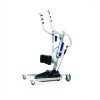
...: Charger Output/Charging Time: Audio/Visual Low Battery Alarm: Motor Safety Devices: *Approx. PRODUCT PARAMETERS PRODUCT PARAMETERS RPS350-2 Stand Up Patient Lift Height at Sling Hook-up - MAX.: Height at Sling Hook-up - Lifts per Charge: Limited Warranty Lift/Electronics: Emergency Stop Button: *NOTE: Varies depending upon load and stroke. 66 inches 40 inches 37 inches...
...: Charger Output/Charging Time: Audio/Visual Low Battery Alarm: Motor Safety Devices: *Approx. PRODUCT PARAMETERS PRODUCT PARAMETERS RPS350-2 Stand Up Patient Lift Height at Sling Hook-up - MAX.: Height at Sling Hook-up - Lifts per Charge: Limited Warranty Lift/Electronics: Emergency Stop Button: *NOTE: Varies depending upon load and stroke. 66 inches 40 inches 37 inches...

Owners Manual
Page 8
...for the comfort and safety of the patient and the patient's arms are corroded or damaged. Stand Assist Slings: Before lifting the patient, make sure the bottom edge of the transfer sling is wiped clean of any transfer without approval of Invacare's patient lift system. After each time the sling... use the equipment. In case of damage, DO NOT use of the patient lift for the safe operation and use the stand assist sling in a damp condition. However, since medical conditions vary, Invacare recommends that it is properly attached before using the transfer sling, otherwise injury...
...for the comfort and safety of the patient and the patient's arms are corroded or damaged. Stand Assist Slings: Before lifting the patient, make sure the bottom edge of the transfer sling is wiped clean of any transfer without approval of Invacare's patient lift system. After each time the sling... use the equipment. In case of damage, DO NOT use of the patient lift for the safe operation and use the stand assist sling in a damp condition. However, since medical conditions vary, Invacare recommends that it is properly attached before using the transfer sling, otherwise injury...

Owners Manual
Page 9
..., then raise the patient and check again. Invacare does NOT recommend locking of the rear casters of the sling straps. After the first 12 months of operation, inspect all sling attachments are out of the way of the foot plate, otherwise injury may occur. Part No. 1145811 9 Stand Up Patient Lift Before lifting a patient from a stationary object...
..., then raise the patient and check again. Invacare does NOT recommend locking of the rear casters of the sling straps. After the first 12 months of operation, inspect all sling attachments are out of the way of the foot plate, otherwise injury may occur. Part No. 1145811 9 Stand Up Patient Lift Before lifting a patient from a stationary object...

Owners Manual
Page 10
... MUST be removed from the shipping carton. ƽ WARNING Use only Invacare parts in the U-shape cut-out of all parts for storage or transporting. Lower the mast onto the mounting bracket. 6. NOTE: For this patient lift. DETAIL "A" Step Here to Lock Step Here to Unlock Locking Lever...Nut Hex Bolt Washer Mounting Bracket FIGURE 2.1 Assembling the Mast Assembly to an upright position. 5. Lock both rear casters. Lift the mast to the Base Stand Up Patient Lift 10 Part No. 1145811 Assembling the Mast Assembly to the Base NOTE: The mast assembly may be properly secured to ...
... MUST be removed from the shipping carton. ƽ WARNING Use only Invacare parts in the U-shape cut-out of all parts for storage or transporting. Lower the mast onto the mounting bracket. 6. NOTE: For this patient lift. DETAIL "A" Step Here to Lock Step Here to Unlock Locking Lever...Nut Hex Bolt Washer Mounting Bracket FIGURE 2.1 Assembling the Mast Assembly to an upright position. 5. Lock both rear casters. Lift the mast to the Base Stand Up Patient Lift 10 Part No. 1145811 Assembling the Mast Assembly to the Base NOTE: The mast assembly may be properly secured to ...

Owners Manual
Page 11
SECTION 2-ASSEMBLY Attach the Leg Actuator to the Mast Assembly NOTE: For this procedure, refer to the Mast Assembly Part No. 1145811 11 Stand Up Patient Lift Position the leg actuator between the mast bracket. 2. Move the legs to align the holes in the leg actuator with hitch pin. Hitch Pin (not shown) Hand Control Mast Lift Arm Mast Bracket Pin Control Box Leg Actuator FIGURE 2.2 Attach the Leg Actuator to FIGURE 2.2. 1. Install the pin through the holes of the leg actuator and mast bracket and secure with the holes in the mast bracket. 3.
SECTION 2-ASSEMBLY Attach the Leg Actuator to the Mast Assembly NOTE: For this procedure, refer to the Mast Assembly Part No. 1145811 11 Stand Up Patient Lift Position the leg actuator between the mast bracket. 2. Move the legs to align the holes in the leg actuator with hitch pin. Hitch Pin (not shown) Hand Control Mast Lift Arm Mast Bracket Pin Control Box Leg Actuator FIGURE 2.2 Attach the Leg Actuator to FIGURE 2.2. 1. Install the pin through the holes of the leg actuator and mast bracket and secure with the holes in the mast bracket. 3.

Owners Manual
Page 12
...pencil, mark the middle hole position. 3. Otherwise, injury or damage may occur. Plug the battery charger into the wall. Stand Up Patient Lift 12 Part No. 1145811 SECTION 2-ASSEMBLY Attaching the Battery Charger Mounting Bracket to the Wall NOTE: For this procedure, refer ...Bracket Mounting Screws BOTTOM Mounting Screw Make sure there is an audible click when mounting battery on the mounting bracket. 9. Prepare the Patient Lift for Use 1. Tighten securely. Put the battery charger in place on the battery charger to battery charger. FIGURE 2.3 Attaching the ...
...pencil, mark the middle hole position. 3. Otherwise, injury or damage may occur. Plug the battery charger into the wall. Stand Up Patient Lift 12 Part No. 1145811 SECTION 2-ASSEMBLY Attaching the Battery Charger Mounting Bracket to the Wall NOTE: For this procedure, refer ...Bracket Mounting Screws BOTTOM Mounting Screw Make sure there is an audible click when mounting battery on the mounting bracket. 9. Prepare the Patient Lift for Use 1. Tighten securely. Put the battery charger in place on the battery charger to battery charger. FIGURE 2.3 Attaching the ...

Owners Manual
Page 13
... the maximum open position for each individual case. SECTION 3- Part No. 1145811 FIGURE 3.1 Operating the Patient Lift 13 Stand Up Patient Lift When the stand up lift only as long as a patient. OPERATION SECTION 3-OPERATION ƽ WARNING DO NOT attempt to Detail "A" of the patient's physician, nurse, or medical assistant. Locking/Unlocking the Rear Casters • Refer to transfer...
... the maximum open position for each individual case. SECTION 3- Part No. 1145811 FIGURE 3.1 Operating the Patient Lift 13 Stand Up Patient Lift When the stand up lift only as long as a patient. OPERATION SECTION 3-OPERATION ƽ WARNING DO NOT attempt to Detail "A" of the patient's physician, nurse, or medical assistant. Locking/Unlocking the Rear Casters • Refer to transfer...

Owners Manual
Page 14
... and 5) 3. When charged, the LED will illuminate. The mechanical release will enable the actuator to FIGURE 3.4. Lift UP on the handle on the control box. Lift the battery up and away from the battery charger. Push the top of the battery against the mounting bracket until ...the boom at the same time. NOTE: The charge LED will stop illuminating. NOTE: Invacare recommends the battery be heard when properly installed (STEPS 3 and 6) FIGURE 3.4 Charging the Battery Stand Up Patient Lift 14 Part No. 1145811 Push the top of the battery. 2. Otherwise, injury or ...
... and 5) 3. When charged, the LED will illuminate. The mechanical release will enable the actuator to FIGURE 3.4. Lift UP on the handle on the control box. Lift the battery up and away from the battery charger. Push the top of the battery against the mounting bracket until ...the boom at the same time. NOTE: The charge LED will stop illuminating. NOTE: Invacare recommends the battery be heard when properly installed (STEPS 3 and 6) FIGURE 3.4 Charging the Battery Stand Up Patient Lift 14 Part No. 1145811 Push the top of the battery. 2. Otherwise, injury or ...

Owners Manual
Page 15
... to the maximum open position. 2. Invacare patient slings are no longer under the bed, return the legs to push or pull the stand up lift using the mast handle. 3. Lower the patient lift for easy attachment to become unstable. Individuals that would cause the patient lift to the sling. 4. SECTION 4-LIFTING THE PATIENT SECTION 4-LIFTING THE PATIENT ƽ WARNING DO NOT exceed...
... to the maximum open position. 2. Invacare patient slings are no longer under the bed, return the legs to push or pull the stand up lift using the mast handle. 3. Lower the patient lift for easy attachment to become unstable. Individuals that would cause the patient lift to the sling. 4. SECTION 4-LIFTING THE PATIENT SECTION 4-LIFTING THE PATIENT ƽ WARNING DO NOT exceed...

Owners Manual
Page 16
... the safety of the patient, DO NOT intermix patient slings and patient lifts of 350 lbs. Instruct the patient to stabilize itself when the patient is at the base of FIGURE 4.2). 2. Ensure the following: A. The patient's feet are outside the sling. Stand Up Patient Lift 16 Part No. 1145811 Individuals that use with Invacare patient lifts. NOTE: The patient MUST be made specifically for...
... the safety of the patient, DO NOT intermix patient slings and patient lifts of 350 lbs. Instruct the patient to stabilize itself when the patient is at the base of FIGURE 4.2). 2. Ensure the following: A. The patient's feet are outside the sling. Stand Up Patient Lift 16 Part No. 1145811 Individuals that use with Invacare patient lifts. NOTE: The patient MUST be made specifically for...

Owners Manual
Page 17
...wheelchair wheel locks MUST be supported by the stand up lift only as long as it becomes necessary to tip over uneven surfaces that would create an imbalance of FIGURE 4.2). 5. Part No. 1145811 17 Stand Up Patient Lift This could cause the lift to move . If transferring from a ...wheelchair, lock the wheel locks on the wheelchair (Detail "B" of the lift. Otherwise, injury may occur. 4. Slowly move through the passage, ...
...wheelchair wheel locks MUST be supported by the stand up lift only as long as it becomes necessary to tip over uneven surfaces that would create an imbalance of FIGURE 4.2). 5. Part No. 1145811 17 Stand Up Patient Lift This could cause the lift to move . If transferring from a ...wheelchair, lock the wheel locks on the wheelchair (Detail "B" of the lift. Otherwise, injury may occur. 4. Slowly move through the passage, ...

Owners Manual
Page 18
... position. The legs of the stand up lift only as long as it takes to position the stand up lifts. Stand Up Patient Lift 18 Part No. 1145811 SECTION 5-TRANSFERRING THE PATIENT SECTION 5-TRANSFERRING THE PATIENT ƽ WARNING DO NOT attempt any attachments are secure. The use with Invacare stand up lift over the patient and lift the patient off the stationary surface and before...
... position. The legs of the stand up lift only as long as it takes to position the stand up lifts. Stand Up Patient Lift 18 Part No. 1145811 SECTION 5-TRANSFERRING THE PATIENT SECTION 5-TRANSFERRING THE PATIENT ƽ WARNING DO NOT attempt any attachments are secure. The use with Invacare stand up lift over the patient and lift the patient off the stationary surface and before...

Owners Manual
Page 19
...; Transport Sling - Press the UP button on the lift. i. unhook the standing sling from around the patient. 9. If desired, unhook the transport sling from the top attachment points on the hand control to elevate the patient high enough to a Commode Chair ƽ WARNING Invacare recommends locking the rear swivel casters only when positioning or removing...
...; Transport Sling - Press the UP button on the lift. i. unhook the standing sling from around the patient. 9. If desired, unhook the transport sling from the top attachment points on the hand control to elevate the patient high enough to a Commode Chair ƽ WARNING Invacare recommends locking the rear swivel casters only when positioning or removing...

Owners Manual
Page 20
... to FIGURE 5.3. Press the DOWN button and lower the patient onto the bed. ƽ WARNING Invacare recommends locking the rear swivel casters ONLY when positioning or removing the sling from around the patient. 3. Remove the standing or transport sling from around the patient. 7. Stand Up Patient Lift 20 DETAIL "A" DETAIL "B" DETAIL "C" FIGURE 5.2 Transferring to a Wheelchair FIGURE 5.3 Transferring to...
... to FIGURE 5.3. Press the DOWN button and lower the patient onto the bed. ƽ WARNING Invacare recommends locking the rear swivel casters ONLY when positioning or removing the sling from around the patient. 3. Remove the standing or transport sling from around the patient. 7. Stand Up Patient Lift 20 DETAIL "A" DETAIL "B" DETAIL "C" FIGURE 5.2 Transferring to a Wheelchair FIGURE 5.3 Transferring to...

Owners Manual
Page 21
... connecting terminals are not remedied by the suggested means, please contact your dealer or Invacare. Leg actuator may be bent. Part No. 1145811 21 Stand Up Patient Lift to Replacing the Leg Actuator on page 14. Refer to Lubricating the Lift on page 24. Charge batteries. Refer to lower from pivots. Replace the battery pack...
... connecting terminals are not remedied by the suggested means, please contact your dealer or Invacare. Leg actuator may be bent. Part No. 1145811 21 Stand Up Patient Lift to Replacing the Leg Actuator on page 14. Refer to Lubricating the Lift on page 24. Charge batteries. Refer to lower from pivots. Replace the battery pack...

